Sunday 18 October 2015

An advancing tail

Some  good progress this week.

First job was to complete the Nav antenna installation in the fin cap.  When I finally get to avionics in about 18 months (maybe that's a bit hopeful!), I intend to have a Garmin GNC255 Nav/Com so that I can have a VOR/ILS capability in addition to GPS - just nice to have a back-up for when GPS goes down as I've experienced several times in the PA28.
I don't know yet whether the displays will be Garmin G3X Touch or Dynon Skyview.


Next job - complete the fibreglass work for the fin-cap and rudder.


The fin cap now has anchor nuts instead of being riveted so it can be easily removed for access to the antenna.  The two antenna rods screw into the antenna base once the cap is installed, and grub screws accessible through the small forward holes are used to lock the rods in place.  Hopefully I can find some discrete plastic plugs to blank the grub-screw holes to keep moisture and inspects out!

The horizontal stabiliser spar box parts were painted (the first items using the two-pack epoxy primer with all of the forced-air breathing hassle) and fully assembled.


The assembled upper and lower spar caps (the lower is the new one I've had to re-make).

The front and rear spars sections were then fitted with anchor nuts for the hinges and control horns.  The mass-balance arm mounts (the white un-equal hexagonal parts in the pictures below) were installed and then the sections were riveted to the spar box.


The spar assembly then had the spar brackets and forward and rear ribs attached.  I did have to de-rivet one end-rib and re-do it as a small tab folded ended up on the wrong side of the spar.


Last job before the skins can be installed was to install the hinge brackets.   The spacers bolted between each side of the hinges have to be cut from a length of tube, and getting them precisely the right length and with square ends so they don't distort the hinge brackets was a bit of a challenge.  I found the best way was to finish the ends on a bench sander fitted with a right-angle guide - something that came in my Gumtree tool bonanza! 
The black lines on top and the 4 loose bolts are where the control horns will be fitted later.


The tail plane skins have to wait until the skeleton has been inspected and this won't be for a few weeks.  In the meantime, I will build the rear fuselage cone and both items can be inspected at the same time.  I'm just starting to prepare the fuselage frames.


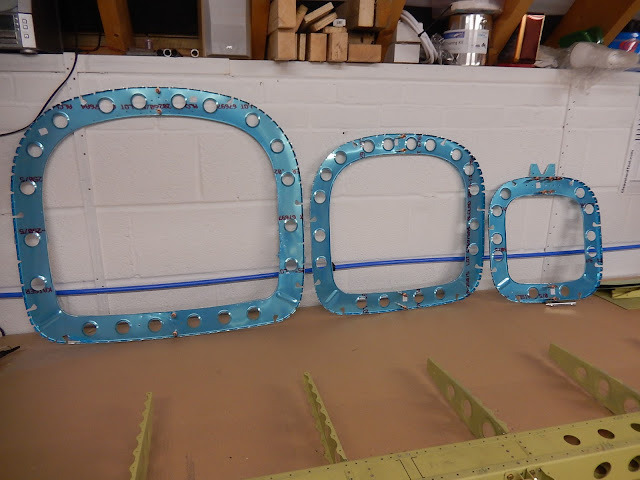
You can get an idea of scale when looking at the bench with the stabiliser skeleton and fuselage frames together.  


The stabiliser skeleton is 8 feet wide - this being the maximum width you can tow on US highways.  I think this towing width limit also applies in the UK, but I expect to take the completed parts to the airfield separately and assemble them on site (they will be trial-fitted at home of course to ensure it's just final assembly for flight at Fairoaks.

This week should see more progress on the rear fuselage cone and hopefully getting parts primed and ready for assembly.

Tuesday 6 October 2015

2 steps forward ....

After a short break from RV activity with a holiday in Devon (nice place to cycle along the Tarka Trail), and also some paying work to address, it's back to aeroplane building.
Of course, not everything goes to plan, so I've made a couple of un-forced mistakes. Nothing too serious but a bit time-consuming to put right.


Unfortunately I'd countersunk the wrong hole in the horizontal stabiliser lower spar cap (a
structurally important bit to the uninitiated!).  I took the picture and checked with the factory to see if the situation could be salvaged, but the response from Vans was 'Scrap it'.  Fortunately we had the right material at work so I've been able to make a replacement using the damaged part as a pattern, so other than 4 hours of additional work, there's no lasting damage.
For the bits I'd already completed, it was time for the first inspection by my LAA inspector.  There are laid-down tasks that have to be overseen and signed-off before moving on and initially, these were inspection of the completed fin and rudder skeletons before the skins were installed.  The LAA have produced an RV12-specifc inspection document which was the first my inspector had seen - it's probably based on information he'd provided!
Fortunately there were no issues on these parts, so I've been able to progress and finally rivet the skins.
Here's the completed rudder
And the vertical stabiliser (the fin).
I've also managed to complete the two halves of the anti-servo tab (this forms the small control surface on the back of the tail-plane and is controlled by the pitch trim servo motor - there is no manual pitch trim in an RV12.  The control rod goes between the two brackets in the centre of the picture.

The hinges are still using the remains of my green primer in a can - easier than setting up the paint gun for just two small parts.  They were painted with a gash rod inserted through the hinge-pin hole to make sure it didn't get clogged up.
 I also want to fit a Navigation antenna inside the top of the fin, so this means adding an antenna mounting plate and modifying the fin cap.

This is the doubler plate for the Nav antenna.  The antenna will fit above this plate using two 15mm high x 20mm diameter aluminium spacers.  Small holes in the fin cap will allow the antenna elements to be installed once the fin cap has been fitted.

Next part is to complete the fibreglass tips for the fin and rudder.  These come 'as removed' from the moulds. After a few hours of cutting sanding and drilling, it's time to see if the parts all go together and check if the rudder and fin caps interfere when the parts move on the bearings.  It looks like we finally have some real aeroplane parts!


Real aeroplane pieces!

I've decided to change the type of primer I'm using again!  The original green primer in cans is not very efficient and will work out very expensive.  The later single-part Acid-etch grey primer really doesn't stick as well as I'd like.  I don't want to go through the pain of using Alumi-prep and Alodine, so all future parts will be aviation yellow epoxy primer which seems to be the toughest stuff available.  This does mean using a forced-air breathing mask as the two-pack primer is pretty nasty stuff.  Someone in the future is going to wonder what was going on with so many different colours inside hidden parts of the aircraft!
Prior to getting on with the new parts for the horizontal stabiliser, I've also improved the paint area by creating a large paint box with a mesh top so that the air from the paint gun doesn't blow small pieces around the room!
The paint box is 2.5M wide and 800mm deep and 150mm high with the meshed top on hinges, so should take the largest parts and allow bits to hang-down when opened.  You can see from the yellow mist that I've been experimenting and it does work much better than the paper-covered pasting table.
For the next week or two, I'll be working on the horizontal stabiliser skeleton (tail-plane in common-speak) and this also needs inspection prior to being skinned.