Friday 21 April 2017

Firewall and longerons

A brief update on this week's activities.  Not too much visible progress but the main lower fuselage is now ready for its stage inspection.

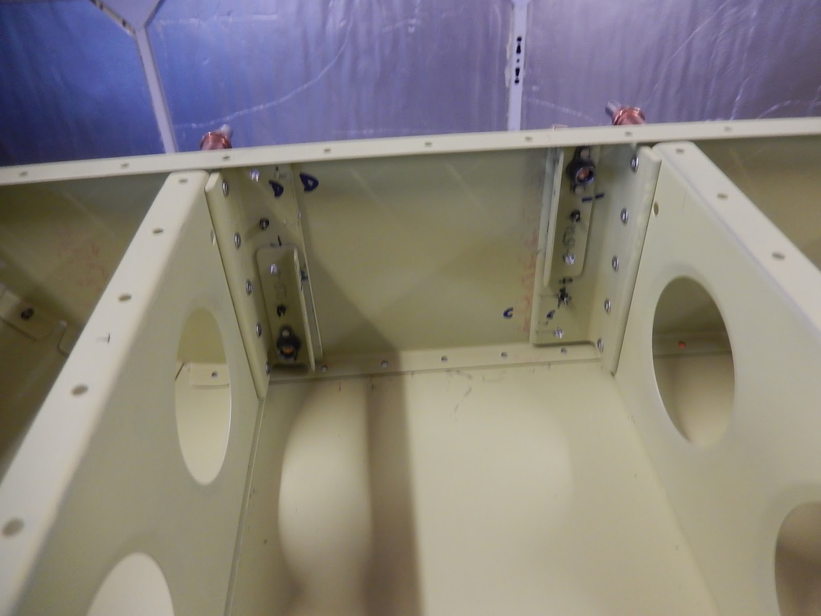
First job was to fit the autopilot roll servo brackets at the back of the baggage bay floor.

 Here are the servo brackets attached to the aft floor bulkhead.  The servo control operating arm will move the flaperons.  The servo motor won't get installed until the tail cone is attached and all drilling etc is complete.

Now I've moved on to building the forward lower fuselage section on the bench.  This part comprises the lower firewall (stainless steel and very sharp!), engine/undercarriage mounts, forward floor (where your feet sit on the pedals) and the centre tunnel below the throttle. 

This picture shows the right-hand lower engine/undercarriage mount fixing inside the tunnel. Below the engine mount on the floor you can see a set of holes for anchor nuts - this is where the bottom of the nose landing gear will be bolted on from underneath the fuselage.

The assembled firewall with both lower engine mounts, tunnel sides, forward floor and fuselage lower side skins.  The hole on the left side of the tunnel floor is for the transponder antenna.

 The lower firewall with the lower fuselage side skins cleco'd in place ready for riveting.

 Now I've temporarily attached the firewall structure to the centre tub.

 Looking forward into the foot wells at the inside of the firewall.  When you're seated, one foot goes each side of the rib running forwards across each foot well floor panel.

A final view of the riveted structure with the additional engine cowling brackets on the bottom flange of the firewall.  The is a diagonal stiffener to add on the right side of the firewall (left side of the picture.  The matrix of holes on the opposite side is for the heater to let air into the cockpit.  On top of the firewall is the temporarily cleco'd firewall shelf where the rudder pedal support brackets will be fitted in the next step.

Having completed the lower fuselage and ready for inspection, I've moved on the preparing the main fuselage side skins and other parts. 


 To start, you have to make two longerons from 7-feet lengths of thick 1" extruded aluminium angle.  I was dreading this as there are loads of discussions on the Vans forum about the challenges this step creates.  You have to open the 90 degree angle to 95.4 degrees over the first 12 inches, plus add a 2.7 degree twist, then create an accurate curve over about 40 inches for the cockpit sidewall.  The picture shows the left longeron almost completed after much hassle!

Over the next week or two, I'm going to prepare all of the remaining fuselage parts so I can have a large assembly session and then it's into fitting out plumbing and wiring!

Thursday 13 April 2017

More centre fuselage.

Since returning from holiday I've continued making good progress on the main fuselage structure, with probably the most concerted period of activity in the last 12 months. 


Control tube installed onto the 2 bearing supports.  The deliberate mistake in this picture is that both bolts should have the heads outboard and the one on the right is facing the wrong way.  I corrected this before moving on!  Once the aircraft skin is fitted, it won't be possible to get this tube out again.  Also if a bearing in the support bracket needs changing, the whole bearing bracket will need to be drilled off and removed from the aircraft - a bit of a dockyard job!
Looking rearwards through the hole in the seat front bulkhead (below the pilot's knees) where the pilot's control stick will fit onto the control tube.

Lots of parts preparation for the lower fuselage side skins and the fuselage step floor.  

 
The fuselage structure upside-down and showing the left-hand lower side skins.  Lot's of individual overlapping sections are used to take up the complex curve.  It's a bit like an Armadillo's armour!  On the right you can see the step floor ribs.

With both lower side skin sections in place, it's time to fit the main belly skin.  This is probably the largest individual skin in the kit.   I didn't count but I think there must be about 500 rivets holding this on and it took several hours and aching hands putting in and removing cleco pins!

Looking down on the belly skin (top of the picture is to the rear of the aircraft) showing the access panels for fitting the main undercarriage, rigging controls etc.  The yellow triangular plates are additional doublers to help spread the load between the skin, floor ribs and centre section bulkheads.  The blue plastic was removed and the skin painted underneath the doublers before they were finally riveted in place.  Left of centre you can see a large round hole - this is for the VHF antenna connector.

With the belly skin installed, the fuselage is turned the right way up and work commences on the step floor bulkhead and the step reinforcing angles.  Here the step anchor nuts and mounting angles are being installed.

The steps need to be leveled before drilling the final hole for the top mounting bolt.  Here I've checked the fuselage is level on the trestles and then set the step as close the level as I can manage - 0.3 degrees.  I can't get it dead-on as the top of the step arm would stick above the bulkhead but it's close enough for me.
If you've noticed, the steps are in front of the seats, meaning you access the cockpit by climbing onto the wing from the front - directly behind the propeller, so not something to do with the engine running!

Both steps fully installed.  They now come off for painting and to make continued building easier, and won't get fitted for good until we have the aircraft in the hangar at the airfield for finally assembly prior to flight.  My kit was delivered with the original step design, which has subsequently been updated to improve resistance to cracking at some welds (possibly due to heavier pilots than I).  The change to the step design doesn't affect the mounting points (although the bolts are different lengths which briefly confused me as I'm working to the latest drawings which call out shorter bolts and they weren't long enough!).  I'm going to stick with the steps I've got initially and just keep a good eye on them.  

With the step structures completed, the step floor panels can be fitted.  Daughter's boyfriend James got involved here, final-reaming #30 all of the holes and pulling the rivets. With the floor down, the nylon bushes which protect wiring, control cables and pipework from chafing on the metal structure are installed into the bulkheads.  In this view you can also see the pilot's and co-pilot's control stick connections to the control tube.

Another small bracket to install at this stage - the electric fuel-pump mount, which is in the centre tunnel below the baggage bay floor.  There's also a mechanical pump on the Rotax engine.

I needed some help to fit the six studs into the cockpit centre tunnel.  These will be used to mount nylon blocks which secure the fuel and brake pipes.  James drew the short straw and is fitting the nuts to the studs above his head whilst yours truly holds the screwdriver!

I've started preparing all of the parts for the remaining forward lower fuselage section (the floor below the rudder pedals) and the engine firewall, so hopefully I'll have this section completed and ready for a stage inspection in the coming week.


Saturday 1 April 2017

Main fuselage continued.

Back from holiday and I started by preparing another load of fuselage parts in anticipation of a big assembly session.

To start with, I installed the wing spar box closure pieces and fitted the wing-spar rollers which aid quick wing removal and installation.

 This is the left side of the spar box.  The cockpit roll bar will fit on top of the box-pillar.  The taped-off holes are the large bushes where the wing securing pins are fitted.  I masked them to keep then free of paint when originally priming the parts and will leave them masked until the cockpit has been finally painted grey.

This picture shows the left wing-spar roller.  There is an aluminium tubular spacer inside the roller to ensure it doesn't stop rotating when the securing bolt is tightened.  In this view you can also clearly see the brackets which hold the seat-belt lap-straps for both occupants.

A view from the right side of the fuselage through the spar box showing both rollers and the spar guide blocks.  Note that the rollers fit in opposite directions.

Next job is to assemble to control column bulkhead with the front stub-spar pockets, control column bearing brackets etc.  I didn't take any stage pictures so here is the finished product!

Aft side of the left wing front stub-spar pocket showing the reinforcing structure. 

Looking into the pocket for the left wing front stub-spar.  In this view you can see the additional bracing structure on the forward face of the bulkhead.

Final view of the stub-spar pocket reinforcing, looking aft on the left side on the 
fuselage.  The holes with red edges are where rivets mustn't be installed at this stage,
so it's my way of making sure I don't put them in by mistake!

Left-side control tube bearing bracket.  The bearing bracket is assembled before being riveted to the bulkhead.  Trying to flush-rivet the four rivets around the bearing was a challenge and took several attempts.  I do wonder how you'd change a worn bearing as a maintenance action in the future - quite a lot of dismantling would be required.
The two horns on the plate in the centre of the bearing bracket are the elevator control limit stops.

 
This is the reinforcing plate around the control column aperture.

Looking down on the seat pans with the control bulkhead cleco'd in place ready for riveting.  You can see how many anchor nuts are needed for removable access panels.  I still have a few hundred in the parts bin! 

 A view on the control bulkhead looking aft .  The next job is riveting this to the seat base ribs before adding six more ribs and the cockpit floor step.

Final view for this section, with a view that covers the front and rear stub-spar pockets and the main spar box.    If you've followed what's gone on so far, you'll realise that the left side of the picture is the front of the aircraft.  Not long now before I can sit in the seat and make aeroplane noises and push a control column around even if it won't actually look like an aircraft!
Having worked on Cessnas and Pipers from the last 25 years, the RV12 cockpit floor seems to be a much more complex structure (perhaps for crash-worthiness?) even if the materials seem much thinner.