Wednesday, 30 December 2015

A bit of Chrismas cheer.

Welcome to my last post of 2015.  Although it's the Christmas holidays and I didn't foresee much progress, I got in a few hours before Christmas Day and a few more since then, so I have been able to get the tail cone completed and my next stage inspection passed by Jerry.  As I don't have a target for completion (it's meant to be a fun hobby after all), I'm pretty pleased with progress so far.

First task since the least visit was competing preparation and painting of the remaining skins and top rib.  

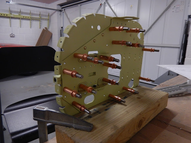
Fitting anchor nuts to the fin attachment rib which will go on the top tail cone skin

After the upper side skins were pinned in place, it's time to start out-fitting the tail cone. There's not a great deal in the rear - control cables for rudder and elevator, wiring for the electric trim, nav antenna cables and static pipework.

Strings fitted to pull-through the elevator and rudder cables (in about a year!).  Also installed the pitch trim electric cable loom and the static port pipes to the ADAHRS. 

You can just make out the inside of the left static port.

This is the right static port from the outside - it's a pop rivet with an over-sized head and the mandrel pushed out. 

Now the final top skin is pinned in place, all holes match-drilled and then the skin removed again to deburr the holes.  Finally, it's back on again and ready for riveting.

Top skin clecoed in place and ready to rivet. 

You can see the remaining pins securing the skins to the fuselage frames.

The completed tail cone ready for inspection.

A top view of the fin attachment rib.  The skin below the rib has been primed to prevent corrosion.  The antenna connector is for the nav antenna in the fin cap, and allows for easy installation or removal of the fin.

Inside the completed tail cone.

My next job is to skin the horizontal stabiliser (HS).  The skins are already prepped and painted.  Moving on, it'll be a trial-fit of the fin/rudder and HS to the tail cone.  At this stage, it will look like the complete rear-end to an aircraft!  Once this is done, I have to deal with the trim motor mountings and then make the tail cone fibreglass fairings fit (apparently a bit long-winded to get good alignment with all of the securing brackets) .  I reckon this will take me to the end of January, and then it'll be time to start on the wings.

To all readers - thanks for visiting and my best wishes for a Happy New Year.

Monday, 14 December 2015

Back underway

Unfortunately I've had an unscheduled delay due to hand and knee pains.  
After a bit of medical investigation, it transpires that I've got arthritis in the hands and right knee, and other problems with my left knee!  However, after a large steroid jab in the backside and a couple of additional weeks waiting, my hands at least are improving, so it's back to work.  Fingers crossed the jab will work long-term - only time will tell.  
These problems all started before the kit arrived, so I can't blame the aircraft.  The physio looking after my knees reckons it's because I've stopped flying a desk and got active after many years being sedentary.  

First job on re-start was to complete the trial fit of the horizontal stabiliser skins and match-drill all final holes prior to painting.


This is 8 feet wide.  I think we might have a problem getting the aircraft assemble in the garage!

Next job was to assemble the rear bulkhead which has the hinge bearings for the horizontal stabiliser, plus the rear tie-down bracket, hinges for the trim-tab motor and the main attachment for the fin.  It's a double-skinned assembly with loads of rivets of different types and sizes, so great care needed to get the right ones in the right holes.


So moving on and it's time to deal with the biggest part so far - the rear fuselage cone.  This is about 9 feet long (it goes from the back of the cabin to the tail) and has nine individual skins and three frames plus the bulkhead.

First step is to assemble the previously painted frames.

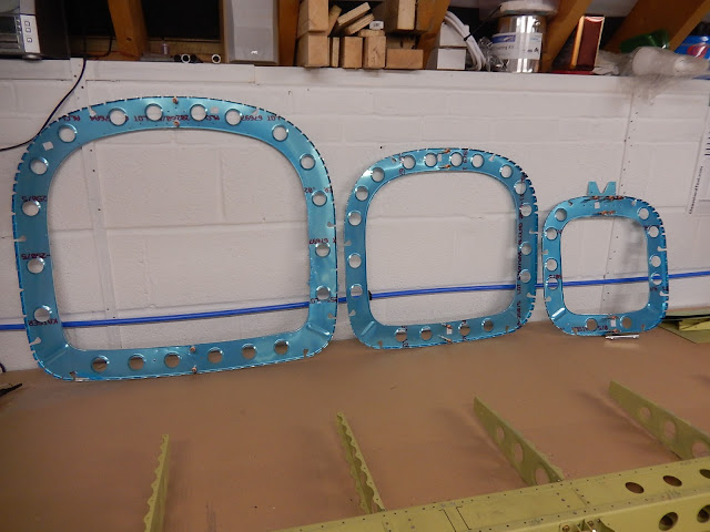
The finished frames.  The V-shaped bracket at the top of the smaller frame is where the front of the fin attaches to the fuselage.

In preparing the skins, I came across an issue which turned out to be a factory error - a first in what has been incredibly accurate production.

We have to fit some J-section stringer extensions to the bottom skins.  As you can see, the holes don't line up.  I thought it must be my mistake as the holes are fine with the stringer outside the skin, but the pictures suggest otherwise.  A review of the builders' forum showed this to be a known issue and my assembly was correct.  It then became a simple re-bending exercise with a couple of blocks of wood and a rubber mallet and all is now good!


Next is to trial-fit the bottom skins.


Then after final match-drilling and deburring, it's time to assemble and rivet together:


The finished product with all lower skin panel rivets installed.  The ones marked with tape and kept for joining this section to the main fuselage.

Now we get to turn it the right way up and start building up the sides.


 Looking inside at the rear bulkhead.  A large counter-balance will protrude through the bulkhead when the horizontal stabiliser is finally installed.

The rear view showing the horizontal stabiliser bearings.

The next job is to add the wiring and plumbing for electric trim and static system, plus the nav antenna cable, before the final skins are fitted.  The next few weeks probably won't see much too progress as the day job beckons with deadlines and of course it's only 11 days to Christmas!

Sunday, 1 November 2015

Steady progress

No big visible changes this week, but lots of preparation of parts which will hopefully lead to a sudden blitz of riveting!

I finished preparing the rear fuselage frames and painting them on one side. 


I also filled pinholes in the fin and rudder fibreglass caps and painted them as well, so these can now be installed.


All parts for the rear fuselage bulkhead have been prepared.  Plenty of trimming and polishing, countersinking for anchor nuts (which support the fin), plus match drilling and deburring all holes.   I trial-assembled the whole thing including the horizontal stabiliser hinge bearings (but unfortunately didn't take a picture).  All parts have been scuffed with red Scotchbrite prior to painting. 


I also completed the tail tie-down bracket which is riveted through both bulkhead sections. This meant cutting the 45 degree chamfer (good use for the bench sander to get the finished surface flat and square), plus notching the side, drilling and tapping the hole at the opposite end where the tie-down ring will be inserted, radiusing all corners and match-drilling all rivet holes to the bulkhead. My metalwork skills are definitely improving (shame about the state of my hands from sharp edges)!


The final task this week was to trial-fit the horizontal stabiliser skins.  All holes (several hundred) need match drilling to the finished size (the delivered punched holes are slightly under-size and won't take the 1/8th rivets) and then it's taken apart again for deburring and for all rough edges to be finished. Then the whole thing is finally cleco'd back together. Everything lined up perfectly.  The accuracy of the kit continues to amaze me!


The plain anti-servo-tab hinge halves fixed to the stabiliser needed to be drilled-off using the guide supplied by Vans.  I messed up the first hinge section by putting the drill guide on upside down (it's the reverse way round from that used on the servo-tabs themselves and identified by some small notches on one edge), resulting in two holes being too close the the hinge pin before I realised my mistake.  I had to get a replacement section of blank hinge and re-do this step.  This time I marked the drill guide with red and green on opposing sides so I didn't repeat the error.  I need the HS semi-assembled so that the rear bulkhead hinge alignment can be checked.  The skin riveting won't happen until Jerry has inspected the skeleton (which means taking it all apart again).


If things go to plan, I'll have the rear bulkhead, three fuselage frames and three lower skins fully painted and maybe even assembled by my next post!

Sunday, 18 October 2015

An advancing tail

Some  good progress this week.

First job was to complete the Nav antenna installation in the fin cap.  When I finally get to avionics in about 18 months (maybe that's a bit hopeful!), I intend to have a Garmin GNC255 Nav/Com so that I can have a VOR/ILS capability in addition to GPS - just nice to have a back-up for when GPS goes down as I've experienced several times in the PA28.
I don't know yet whether the displays will be Garmin G3X Touch or Dynon Skyview.


Next job - complete the fibreglass work for the fin-cap and rudder.


The fin cap now has anchor nuts instead of being riveted so it can be easily removed for access to the antenna.  The two antenna rods screw into the antenna base once the cap is installed, and grub screws accessible through the small forward holes are used to lock the rods in place.  Hopefully I can find some discrete plastic plugs to blank the grub-screw holes to keep moisture and inspects out!

The horizontal stabiliser spar box parts were painted (the first items using the two-pack epoxy primer with all of the forced-air breathing hassle) and fully assembled.


The assembled upper and lower spar caps (the lower is the new one I've had to re-make).

The front and rear spars sections were then fitted with anchor nuts for the hinges and control horns.  The mass-balance arm mounts (the white un-equal hexagonal parts in the pictures below) were installed and then the sections were riveted to the spar box.


The spar assembly then had the spar brackets and forward and rear ribs attached.  I did have to de-rivet one end-rib and re-do it as a small tab folded ended up on the wrong side of the spar.


Last job before the skins can be installed was to install the hinge brackets.   The spacers bolted between each side of the hinges have to be cut from a length of tube, and getting them precisely the right length and with square ends so they don't distort the hinge brackets was a bit of a challenge.  I found the best way was to finish the ends on a bench sander fitted with a right-angle guide - something that came in my Gumtree tool bonanza! 
The black lines on top and the 4 loose bolts are where the control horns will be fitted later.


The tail plane skins have to wait until the skeleton has been inspected and this won't be for a few weeks.  In the meantime, I will build the rear fuselage cone and both items can be inspected at the same time.  I'm just starting to prepare the fuselage frames.


You can get an idea of scale when looking at the bench with the stabiliser skeleton and fuselage frames together.  


The stabiliser skeleton is 8 feet wide - this being the maximum width you can tow on US highways.  I think this towing width limit also applies in the UK, but I expect to take the completed parts to the airfield separately and assemble them on site (they will be trial-fitted at home of course to ensure it's just final assembly for flight at Fairoaks.

This week should see more progress on the rear fuselage cone and hopefully getting parts primed and ready for assembly.

Tuesday, 6 October 2015

2 steps forward ....

After a short break from RV activity with a holiday in Devon (nice place to cycle along the Tarka Trail), and also some paying work to address, it's back to aeroplane building.
Of course, not everything goes to plan, so I've made a couple of un-forced mistakes. Nothing too serious but a bit time-consuming to put right.


Unfortunately I'd countersunk the wrong hole in the horizontal stabiliser lower spar cap (a
structurally important bit to the uninitiated!).  I took the picture and checked with the factory to see if the situation could be salvaged, but the response from Vans was 'Scrap it'.  Fortunately we had the right material at work so I've been able to make a replacement using the damaged part as a pattern, so other than 4 hours of additional work, there's no lasting damage.
For the bits I'd already completed, it was time for the first inspection by my LAA inspector.  There are laid-down tasks that have to be overseen and signed-off before moving on and initially, these were inspection of the completed fin and rudder skeletons before the skins were installed.  The LAA have produced an RV12-specifc inspection document which was the first my inspector had seen - it's probably based on information he'd provided!
Fortunately there were no issues on these parts, so I've been able to progress and finally rivet the skins.
Here's the completed rudder
And the vertical stabiliser (the fin).
I've also managed to complete the two halves of the anti-servo tab (this forms the small control surface on the back of the tail-plane and is controlled by the pitch trim servo motor - there is no manual pitch trim in an RV12.  The control rod goes between the two brackets in the centre of the picture.

The hinges are still using the remains of my green primer in a can - easier than setting up the paint gun for just two small parts.  They were painted with a gash rod inserted through the hinge-pin hole to make sure it didn't get clogged up.
 I also want to fit a Navigation antenna inside the top of the fin, so this means adding an antenna mounting plate and modifying the fin cap.

This is the doubler plate for the Nav antenna.  The antenna will fit above this plate using two 15mm high x 20mm diameter aluminium spacers.  Small holes in the fin cap will allow the antenna elements to be installed once the fin cap has been fitted.

Next part is to complete the fibreglass tips for the fin and rudder.  These come 'as removed' from the moulds. After a few hours of cutting sanding and drilling, it's time to see if the parts all go together and check if the rudder and fin caps interfere when the parts move on the bearings.  It looks like we finally have some real aeroplane parts!


Real aeroplane pieces!

I've decided to change the type of primer I'm using again!  The original green primer in cans is not very efficient and will work out very expensive.  The later single-part Acid-etch grey primer really doesn't stick as well as I'd like.  I don't want to go through the pain of using Alumi-prep and Alodine, so all future parts will be aviation yellow epoxy primer which seems to be the toughest stuff available.  This does mean using a forced-air breathing mask as the two-pack primer is pretty nasty stuff.  Someone in the future is going to wonder what was going on with so many different colours inside hidden parts of the aircraft!
Prior to getting on with the new parts for the horizontal stabiliser, I've also improved the paint area by creating a large paint box with a mesh top so that the air from the paint gun doesn't blow small pieces around the room!
The paint box is 2.5M wide and 800mm deep and 150mm high with the meshed top on hinges, so should take the largest parts and allow bits to hang-down when opened.  You can see from the yellow mist that I've been experimenting and it does work much better than the paper-covered pasting table.
For the next week or two, I'll be working on the horizontal stabiliser skeleton (tail-plane in common-speak) and this also needs inspection prior to being skinned. 


Sunday, 6 September 2015

Vertical stabiliser and other bits

I managed to complete construction of the paint shop over the previous weekend and set about painting the vertical stabiliser parts. This was done with standard green aircraft zinc-chromate rattle cans.  it quickly became apparent that this was neither efficient or easy, as the nozzles are useless and you don't get much paint in a can!


So the next stop was down to a local automotive paint suppliers for advice - what can I safely spray at home?   The answer was 1K acid-etch primer which comes ready mixed and you don't need forced-air breathing kit - a special disposable mask is OK along with goggles.  So suitably equipped, and using the compressor bought from Ebay and a small touch-up gun from Tool Station, I proceeded to prime all of the rudder and anti-servo-tab parts including the skins..  However, as you can see, they're grey!  What matters most is that the primer sticks well and doesn't easily scratch off.  


Rudder parts


Anti-servo-tab parts.

The next step was to finally start assembling some of the painted parts and hopefully see something that resembles an aircraft structure.  I started with the vertical stabiliser hinges and then the main skeleton in accordance with Van's directions.


First solid rivets in the rudder hinges.


Completed vertical stabiliser skeleton


Next job was to trial-fit the vertical stabiliser skin, and voila - something that resembles a finished part! You have to admire the quality of the kit in that all of the pre-punched holes in every part line up just perfectly.

Once the skeleton has been inspected by Jerry (with the skin off again), I can rivet the skin on permanently.  You can also see in the picture that the upper hinge is now fitted and the lower is tied on ready for the next stage.


Assembled vertical stabiliser.

Another job this week prior to fitting the VS skin was to rivet all of the anchor nuts that secure the forward fairing - fiddly work particularly close to the leading edge, and awkward to do on your own, so a good use for cleco g-clamps.


Final job this week was to start assembly of the rudder skeleton.  I only manage to complete the top hinge and rib installation but the rest is cleco'd together,so not much more to do before it can be skinned.

Partly-assembled rudder skeleton.


Upper hinge on the rudder spar - not all rivets face the same direction!

I have a busy time with paying work this week (I have the fund the RV somehow!) and have a weeks holiday coming, so little will now happen for a fortnight.  After that I should make rapid progress to complete the tail section.