Saturday 25 November 2017

Power-on!

It;s about a month since my last post and lots of little things have been progressing and a few milestones achieved.

Firstly, I completed the main electrical system wiring - battery distribution and circuit breakers.  I also completed the G3X display system (less engine sensors) and got power on for the first time.  So now it both rolls around and lights up!

These are the circuit breakers, which replace the standard Vans' supplied fuses along with the Vans' switching unit.  I've actually mounted the breakers on a sub-panel which can be easily removed from the main instrument panel for ease of maintenance.

Rear view of the wired circuit breaker panel - this is before the sub-panel was completed with anchor nuts and painted.  The final version also has insulating strips between each row of breakers as the terminals are all very close together and I need to prevent any shorts.  Now I understand why Jerry's aircraft has the circuit breakers set at 45 degrees and not vertical!

For those that have seen a standard RV12 with the Vans' control unit, this will seem very empty - it's the avionics bay behind the pilot's instrument panel.  My wiring is directly unit-to-unit so cuts out a large number of junction box connectors and consequently also the amount of wire used.   Hopefully it'll make for a more reliable and lighter installation.  However, going off-piste has probably added over 100 additional hours and a couple of months to the build, not including the new instrument panel which is necessitated by the need  to fit UK-mandated standby flight instruments.


And so power-on for the first time.  You can't see the master switch here but the ignition module that takes up the 5 holes on the left is connected up behind the panel.  The only wiring not yet done is for the 6 switches in the centre and I won't complete this until the instrument panel has been covered and labelled, and also wiring a traffic detection system (I have the provisions in place but don't know which box to put on the end of the wires at present).  There is a 25-way disconnect plug for the switches to allow for easy instrument panel removal, so for the moment I'm just using jumpers across pins to simulate each switch as I run through testing.  A bit of the old day job for a change and thankfully no wiring errors!

Here I've got all of the G3X running and most of the configuration complete.  I started with the basic set-up supplied as a down-loadable file by Vans on their website and then modified the config in-situ to suit my specific differences: I have a Nav/Comm radio instead of just a Comm, I have added an extra warning discrete for standby battery activation, and my ammeter shunt is not the Vans version.  I've also chosen to configure the fuel flow feature as Vans has you install the transducer, so why not use it?
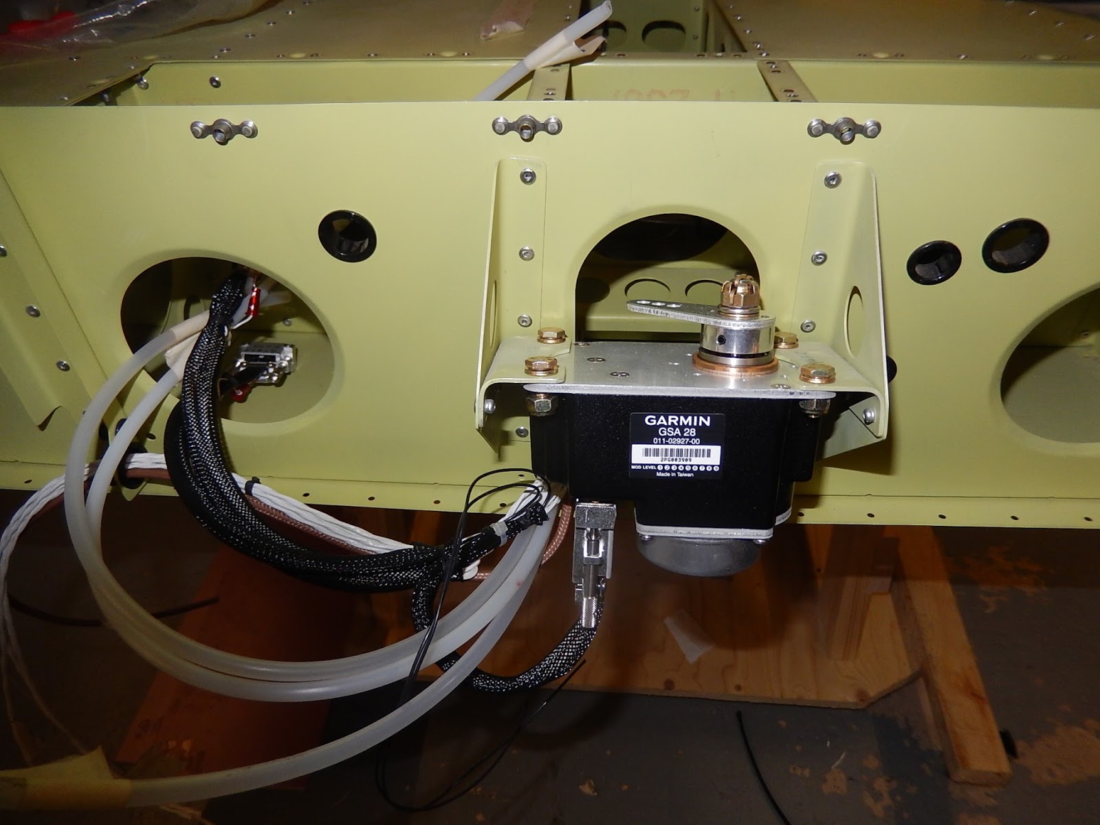
The G3X uses a CAN bus for all of the boxes to talk to each other (originally developed by Bosch for cars) and this worked fine first time, but unfortunately it also allowed me to see instantly that both autopilot serves were defective as they reported 'HARDWARE FAULT'.  This was a know issue to Garmin back in February but they didn't issue any recall of service bulletin - it was down to individuals to see if they had problematic units.  Garmin have supplied me with a brand new pair of servos under warranty (not service-exchange items)  which is a relief as I don't want to start out with used components.

At this point I've taken all of the units and instrument panel back out of the aircraft so I can complete the panel itself - it will be covered in Carbon Fibre film and then labelled.  I've temporarily installed the version 1 (scrap) panel as the outer profile is correct and this will allow me to progress with the canopy installation.

Here's the perspex canopy on the left next to the engine cowlings.  The upper and lower cowlings are sitting inside the canopy frame.   I'm not relishing this next stage!  One mistake or mis-handling and I could scrap the perspex bubble and it'll be very expensive to get another shipped from Oregon.


The first task is to prepare the frame (de-burr etc) and fit the gas-struts which hold it open, and then fit this assembly to the fuselage.  My garage ceiling isn't high enough to do this indoors so outside we go.

Here's the view indoors with the canopy resting against the ceiling - it's going to be awkward if I need to get in and out much!

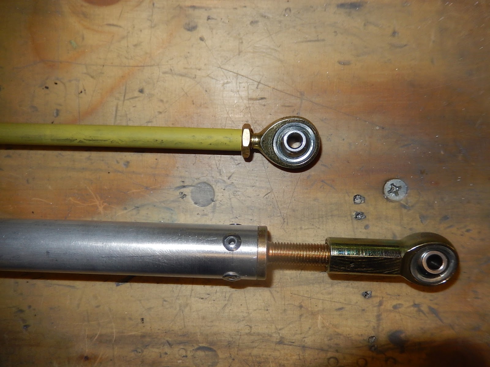
This is a view of the right-side gas strut.  My kit came with the original gas-strut version that had plastic end fittings.  There have been a number of incidents of the end fittings snapping and in one instance, the canopy rotated forwards into the propeller.  Therefore I've bought and installed the up-rated metal-ended struts.

The rear window has to be installed to ensure the canopy is correctly aligned over the roll bar.    Here I've got the canopy in place and held with tape ready to drill the fixing holes.  Finger crossed I don't crack anything!  Getting to this stage is long-winded in adjusting the canopy position, trimming and polishing the edges to ensure the correct clearance all round.  It must have gone on and off a dozen times before I was happy.

So finally the canopy holes in the roll bar and front tube are all drilled and the side skirts have been temporarily fitted.  I've also made the two small handles used to list the canopy. 

Just visible in the pilot's seat (actually on a pile of dust sheets and blankets!) is Deborah who was helping me to drill the canopy sides.

Now it all comes apart again so the frame and all metal parts can be painted before final assembly.  The last and probably most difficult part is to make the front skirt which requires a wet lay-up of fibreglass between the screen and the avionics bay cover.  This will have wait for a couple of weeks so I'm moving on to the engine cowlings.

I started by trimming and sanding the cowling mouldings back to the scribed lines.  This took several hours to do both halves and there wasn't much to photograph.  I got covered in dust but at least I wore a mask so din't inhale it! 
Here's the first trial-fit of the lower cowling.  I needed a lot more space on the garage floor to work on the cowlings as the canopy is now occupying the work bench so the aircraft had to be outside on the drive for most of the day.  That generated a few surprises for passers-by!

This picture shows the alignment of the lower cowling to the right side of the firewall and hinges which will secure it.  It's pretty close already so hopefully not much more sanding needed to get an accurate fit.

That's it for the moment.  More cowling and canopy work over the next few weeks and also a trial-fit of the wings so I can drill the flaperon arms and then fit the fuel tank. 


Saturday 28 October 2017

It's mobile!

My RV12 has finally moved on it's own wheels!  Still loads to do though, so here's a brief update.

First job after the fuselage-joining inspection was to prepare all of the undercarriage parts - the main legs, wheel fairing brackets, nose wheel fork etc.  Unfortunately I didn't take any pictures of the pre-installed parts!

Here's the first part installed - the left main undercarriage leg together with axle and fairing bracket.  Note to self:  Next time, put the brake caliper on BEFORE fitting the fairing bracket!   Installing and tightening the undercarriage bolts is a bit of a headache and I needed to drill a couple of holes in the belly skin, which are listed in an old service bulletin which weren't already present in my kit.  These holes are needed to get a 1/4" drive extension bar and socket onto the bolt heads.


Here's the right main leg with the brake caliper correctly installed.

Next it's time for the nose leg and fork to be fitted.  Although my kit came with an un-used standard fork, I've bought the up-rated nose fork as there have been many reports of the original design cracking.   The bolt with a stack of washers is where the tow bar attaches for ground handling.  The two black fixings at the top of the leg onto the firewall are 3/16" skin pins - being used as temporary fixings until the lower engine mount is bolted on to this location.  These holes will eventually be drilled out to 3/8".
The nose-wheel is free-castoring - there is no directly-coupled steering, so you change direction by use of rudder and differential brakes.

So onto the wheels.  I chose the paint the wheel halves as they'll be hidden inside fairings and open to corrosion if the aircraft eventually ends up living outside.  I used a Lazy Susan (used for cake decorating) to allow the wheels to be rotated when painting and this allowed for a decent finish.
I have no prior experience of assembling split-rim aircraft wheels with tubed tyres so it took a bit of reading the manual and fiddling to get the valve stem in the right place and not pinch the tubes, but finally they all went together OK.   What I also learnt was that I needed some new hex bits in sockets so I could correctly torque the bolts.

 So it's finally on it's wheels!

I just had to take the aircraft outside for it's first view of daylight! 


So moving on, I've continued with the electrical and avionics systems in readiness to fit the instrument panel.  This is needed before the canopy can be installed.

I completed the instrument panel itself by riveting stiffeners above each main screen cut-out, added some anchor nuts and drilled all of the circuit breaker holes.  Now it's primed and ready for the carbon-fibre film to be fitted.

More work proceeding on wiring.  Intercom, both PFDs (pilot and co-pilot main screens), autopilot, transponder and radio are now finished.  The main items to complete are the circuit breakers, switches and the engine interface unit (top left on the bulkhead).

A plan view of the part-completed avionics bay wiring.  Everything starts from the centre where the main aircraft harness comes up through the avionics bay shelf.

This is the Garmin GEA24 - the interface between the engine/airframe sensors and the EFIS screens.  Once the wiring is completed it'll be clipped to the bulkhead to allow the top cover to be installed without chafing. 

This is some of the electrical wiring in the engine bay - for the battery and start contactors, and the ammeter shunt.  The shunt is normally inside the Vans switch/fuse panel but I'm not using that.  Also in the picture are the manifold pressure sensor (top centre) and fuel pressure sensor on the right of the picture with the yellow cap on the pipe fitting. 

I've also temporarily installed the battery - merely to add some weight to the nose now the aircraft is on it's wheels.  Without this it wanted tip onto its tail! 

I took some time away from wiring to finish the braking system by installing the main leg brake pipes and attaching the rigid plastic pipes from the park-brake valve to the undercarriage brackets in the centre section.  I've chosen to use after-market braided flexible hoses on the legs instead of the Vans-specified aluminium pipes as this allows for removal of the brake calipers without needing to bend rigid pipes. 


Finally I completed the internal controls for the flaperons in readiness to trial-fit the wings.  With the wings installed, the flaperon control arms can be match-drilled whilst the controls are locked in a rigging position.  Hopefully I can get the aircraft out of the garage again in the next week and complete this step.

This view is looking down and aft on top of the flaperon controls - the white tubes exit the fuselage sides and engage with the flaperons on the trailing edge of the wings.  The green rods connect to the mixer between the seats which in turn connects to the pilots' control sticks.
I wasn't happy that the two bolts on the end of the green push-rods were in alignment when the controls were in neutral so took the lot out and re-measured/adjusted the rod ends until everything was aligned accurately.  It's difficult to get the price dimension stated in the build manual and surprising how a quarter turn either way on opposite rods can have a dramatic effect.

I'm not proceeding as quick as expected but hopefully will complete the electrics/avionics in the next couple of weeks and start on the canopy.


Sunday 10 September 2017

Fuselage structure completed.

We've been away on holiday and I managed to crack a couple of ribs in my back falling off some steps whilst gardening, but nevertheless good progress made since my last blog entry.  More wiring completed, flying controls almost finished and significantly, the two halves of the fuselage have been joined together!

I've finished routing the fuselage wiring loom and pitot-static pipes to the instrument panel. This is looking forwards/upwards in the centre console.  They go behind and over the rudder pedal assembly which is really awkward, as is installing the small cable guide to the left of the central rudder bar pivot.  Anyway it's all in and ready for terminating at the panel.

I've also installed the control sticks and associated flaperon push-rods (just visible below the white horizontal tube) and the rudder and elevator cables.  I mis-rigged the control stick push-rods initially (mis-read 9 5/16" on my steel rule and set the distance as 9 5/32" instead) which meant the control sticks weren't parallel with the controls in a neutral position. Therefore  I had to strip the sticks and push-rods out and do it again - a real pain as there are spacing washers needed which I ended up super-gluing in place.
The transmit switch wiring is now in.  Not visible are the cycle handlebar grips at the top of the control sticks which also contain the Press-to-transmit (PTT) switches.  Now I can remove the reminder label! 

I've completed all of the headset wiring - this picture just shows the co-pilot's sockets including a stereo jack.  Deborah (SWMBO) doesn't find flying very rewarding, so she can independently listen to an iBook or music whist I manage the radio and get us to somewhere of interest!  It does mean I have to have a separate PS Engineering PM3000)  intercom system which is another deviation from the Vans plans.
I've also added supplementary BOSE headset connectors which allow the use of aircraft-powered ANR headsets instead of using battery packs.  All of this took well over a day to do both seats, whereas using the Van's harness, it could probably have been done in a couple of hours!  Nevertheless I don't have any of the awkward miniature Molex plugs that Vans use and I have additional capabilities.

The last bit of fuselage wiring so far was to terminate the spar pin switches.  These switches are there to warn the pilot if the wing-spar pins aren't secure and prevent the engine being started. My kit came with magnetic reed switches which are meant to be awkward to adjust. Subsequently Vans came out with an upgrade for use with miniature push-button switches (mounted just below the 2 shiny screws) so I've gone with the later system.

This shows the left wing disconnect panel complete with AOA pipe.  I've temporarily fitted the plate so I can mask around the outside ready to prime the skin beneath.  The piece of foam taped to the skin is protecting the Garmin outside-air-temperature probe which can easily be damaged but needs to be fitted now as this can only be accessed through the wing break cover plate.


Now it's finally time to do some serious structural work and join the front and rear sections of the fuselage together.  With some assistance I got the tail cone down from where it's been hanging from the ceiling for the last 20 months and positioned it onto the rolling trolley.


The forward fuselage is still on it's side as I was completing some flying control work.   With the tail cone on the trolley I can move it around single-handed to get the two parts aligned.


I took the opportunity to install the magnetometer and wiring harness into the tail cone and complete the re-worked static pipe system before the two halves were joined - much easier access than doing it lying down though the fuselage under the roll bar.  I also added a disconnect plug for all of the tail cone wiring (magnetometer and pitch trim) and also for the nav antenna so I can just plug the two parts together when the mechanical work is complete.

So on to the fuselage assembly.  Here's a view from the left side of the front and rear fuselage sections cleco'd together and ready to rivet.  Not really visible but also in place are the seat belt shoulder strap fittings either side of the roll-bar brace.

And a view from below.  Setting all of the rivets probably took about a day which includes two lower fuselage panels below the baggage bay which have the exit holes for the flaperon controls.

Main riveting complete and ready for the turtle-deck panels (around the back window) to be installed.
A view looking down gives an idea of the length of the fuselage which now takes up almost the whole depth of the garage.  There will be just enough room to get the engine installed but not the fin/rudder or propeller.

Of course something had to go slightly amiss during the joining process and it's shown here - the top skin should sit over the lower skin.  I didn't notice the error as I pulled the two halves together and it didn't help that I did all of the joining on my own.  Fortunately I spotted it before the turtle-deck panels were installed.  It only meant drilling out 10 rivets and then flexing the skins apart carefully to to get them in the right place. Unfortunately I'd made the same mistake on both left and right sides of the fuselage!

Next job is to install the turtle-deck panels and prepare the rear window.  Here the panels are in place and cleco'd with the perspex window ( a flat sheet which has to be bent to the right shape in situ).  I was very nervous doing this in case I damaged the window but so far so good.  The forward window fixing holes are then match-drilled into the roll bar and then with the window removed, the roll-bar holes are opened-up to final-size and tapped with 6-32 UNC threads for the securing screws.    The window won't finally be installed for a while - access is needed to finish the fuel tank installation and I have to complete painting the roll bar.  I want to leave the painting until the canopy installation is done as that may produce some scratches etc.

Turtle-deck lower and rear edges riveted in place.

Finally with the rear window removed and the fuselage positioned onto both lower trestles where it will live until the avionics are complete and the engine cowlings and landing gear are installed over the next few weeks. Before all of that it's inspection time again.


Friday 4 August 2017

A bit more progress

I've done a bit more wiring (the main harness is now all installed in the fuselage) and I've also started on the flying controls.

 This is the autopilot roll servo installed at the back of the centre fuselage with wiring completed.  If the tail cone was fitted I'd have to do this lying down inside the fuselage at arms length!   I'm adding tail-cone disconnects for the magnetometer, trim motor and Nav antenna so I can just plug them all together when the two part of the structure are jointed together.

 The two connectors on the left are for the attitude/air data computer which hangs on the underside of the baggage bay floor panel.  It will also have 3 plastic pipes (pitot, static and AOA).


Here's the autopilot roll servo below the pilot's seat - we're looking down and the front of the aircraft is to the left. Note to self - fit the connecting rod bolt into the operating arm before fitting the servo next time!

Roll servo viewed looking left across the cockpit.  The troublesome bolt is now visible and wrapped in tape to keep it in place!

The two avionic cooling fans have gone in.  They only use two fixing screws and the instructions say not to over-tighten or the flanges will break.  So I made some spacers from spare brake pipe.

The rats-nest of wiring in the foot-well is growing but I won't deal with this for a while - I'm more bothered about items in the centre fuselage and rearwards so that I can finish these with easy access and get the tail cone attached.


So starting to deal with the controls now that all of the wiring is in the centre tunnel.  First job - paint then install the flap operating arm and mixer assembly. Getting the mixer to clear the wiring bundle was a real headache!

Another view of the flaperon mixer.  You can see the protective cover at the top over the wiring harness - there's just no room left for any extra wiring.   

The flap handle mounting at the rear of the control tunnel (the two lugs are for the seat belts).  Another tight squeeze so the flap handle cross-tube doesn't rub on the fuel pipe (right side) or wire harness on the left.  At least by installing the avionics wing before the controls, I won't have to disturb this or try and feed cables in with the controls attached which I think would be impossible.


The RV12 is designed to met the LSA standard with a maximum weight including fuel and passengers of just 600Kg.  So everything has to be light.  This picture to me seems to take it to the extreme.  At the top is one of the control rods that join the control column to the flaperon mixer for roll control.  It's not much thicker than a pencil!  At the bottom is one of the push-pull rods that goes rear to the flaperon operating arms.

Finally for this week a bit more wiring.  I completed the wing root connections - designed to enable the wings to be quickly removed for transport just like a glider.   Above is the right wing connector

This is the left wing connector complete with a pneumatic pipe disconnect for the AOA (angle of attack) sensor.  I've now just got to terminate the headset sockets and add a BOSE powered socket and then I can close the wing root panels.