I've had a busy few weeks making progress on the fuselage, with installation of systems underway and getting ready to start wiring. At this stage I should be joining the tail cone to the cockpit but that will restrict access so I'm working away from the plan. I'm also changing the design a bit by making a one-piece instrument panel so I can accommodate the dual-screen Garmin G3X Touch display system, GMC307 autopilot controller, Garmin GNC255A Nav/Com radio and the UK-mandated standby airspeed indicator, altimeter and compass.
Firstly, we had a delivery! The firewall-forward kit is here together with all of the remaining parts to complete the kit (other than those that I've just scrapped as you'll read below!).
One crate weighing about 180Kg. Fortunately the lorry that delivered it had a tail-lift and the driver had a pallet truck to manoeuvre the box. It's got everything inside including an individually-crated Rotax 912ULS engine, propeller, battery and loads of assorted pipes, exhaust etc. Need to up my insurance cover now - the engine is worth more than the aircraft!
So, continuing with the rudder pedals and brakes that I'd started to assemble on the bench.
I completed drilling the rudder pedal and brake assembly on the bench. The brake pedal has to be clamped vertically so you can see my digital protractor showing 89.95 degrees - close enough!
Prior to installing the pedal assembly, the forward firewall needs to be sealed to keep any nasty smells and gasses out of the cockpit. Here the edges in the foot-wells are masked ready for the high-temperature sealant. The grille on the left is the cockpit heater entry.
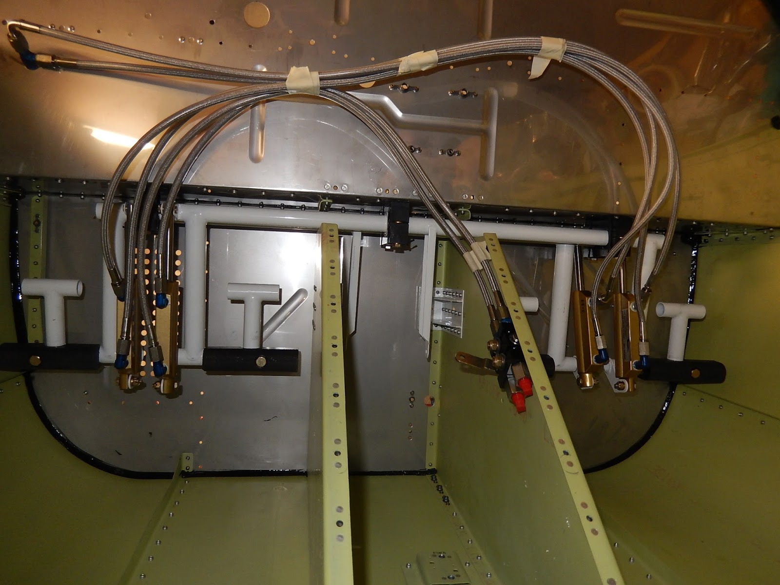
This view shows the pedal assembly installed onto the firewall shelf and the new braided brake hoses from TS Flightlines fitted (although not yet properly clamped in place). In the centre with the red caps is the new parking brake valve. I have to make the next sections of pipe that go to the main undercarriage from rigid plastic pipe - I'm told it's a bit of a pain to do..
So on with installation of fuel components.
This is the fuel valve in the centre floor just in front of the seats. It allows me to shut off the fuel between the tank and the engine. It's also plumbed - I have the make up all of the pipes and flare the ends for the fittings. The smaller pipe is the fuel return line which sends excess fuel back from the engine to the fuel tank.
This is the Red Cube fuel flow transducer - it measures fuel flow rate (litres per hour) so the Garmin EFIS can calculate total fuel used and remaining endurance. On the right is the parking brake valve.
Here is the fuel pump installed under the rear floor and with the pipes attached. Getting these pipes properly lined up and clipped was a bit of a challenge - especially installing the return line union at the top of the picture as you can't really get to the back of the fitting in the spar box to tighten the nut! The fuel tank sits on the floor to the right of the pump.
Finally at the bottom of the engine firewall is the gascolator - a fuel filter and water drain. I'm also adding an additional drain valve directly below the fuel tank using a design created by my inspector Jerry for his RV12 and which has proved very popular.
The black structure on the left of the picture is the engine oil tank bracket and battery box. The final black bracket in the centre is for mounting the GPS antenna under the fibreglass cowling.
Before moving on to the avionics and wiring I decided to put the seats together. I'd prepared the parts months ago so it was just a matter of riveting all of the parts once they'd been painted. I have all of the factory interior trim and cushions stored in a spare bedroom!
Now the avionics shelf and canopy hinge and strut supports get installed. Just a matter of loads of riveting.
Here's the avionics shelf installed and ready for the top cover to go on.The heavy angle bracket supports the canopy gas strut. The canopy hinge is where the beefed-up doubler is fitted just behind the firewall.
More anchor nuts - this time on the sections that rivet to the top cover and to which the top of the instrument panel will be secured.
Here's the top cover in place ready for the instrument panel strips to be riveted. This panel is normally removable for access to the avionics but required sealing along the front edge to prevent water getting in. Must remember to put release agent (wax) on one surface so it'll come off when the sealant dries!
Now I'm starting on the avionics and electrical system wiring as this has to go in before the cockpit flying controls. I need a new instrument panel to locate the main electrical components so that's the first thing to work on.
The panel is made from a single piece of 0.063" aluminium. I used the 3-piece factory parts to create a template which gave me the outline and fixing hole locations. After making the large apertures using a powered nibbling tool, it's down to muscle power with hours of careful filing.
Here's the finished product in place for a first trial fit. Looks good at this point. Knowledgeable RV12 people may notice the lack of a throttle mounting plate on the panel. I've decided to do a split arrangement so the instrument panel can be removed without disconnecting and removing all of the engine controls!
I just had to put the Garmin screens, autopilot controller and ignition/power switch unit in! I'm really looking forward to flying this - it's so much more modern than anything I've flown so far.
Of course all good things come to an end! I had to match-drill the instrument panel centre supports which also support the radio tray back into the new instrument panel, and when I did it, I had the top cover fitted (not shown in the picture) and then drilled back through the supports using my right-angle drill. However, doing this blind and finding the holes using a mirror was a big mistake and two holes ended up out of position. This also meant the supports were scrap and I need to order replacements from the factory. Time to walk away and think about it for a while!

So after a few days away doing other things, it's back to the panel and attempt number two. Here's the main section cut. I've made some changes based on my first experience. I'm altering the switch layout to accommodate a separate fuel-pump switch (not part of the basic kit) and I'm also not using the master switch assembly. I think it will look neater if the ignition components just mount individually though the main panel.
I'm still awaiting new support struts from the factory and will take a different approach in drilling them to prevent the previous mistake.
Here I've marked out the six switch positions and chain-drilled the holes. The waste is easily removed with a sharp chisel and then back to filing!
The nearly-finished article including the new ignition switch cut-outs on the left side but still waiting for circuit breaker holes on the right. I'm making quite a lot of extra work for myself - the factory wiring won't work and the radio rack structure all has to be altered, but I think the overall effect will be worth the effort. I had no choice for at least some of the changes as I have to fit the extra standby instruments and there's no space normally available.
This shows the original ignition panel which normally sits behind the panel though a large square cut-out. I'll still have the control unit itself screwed through the facia but it won't have it's own face-plate. I'm hoping to find a company that will silk-screen-print all of he required legends on the finished panel which should provide a professional finish.
Moving on in the next few weeks should be all cockpit wiring, flying control rods, pulleys and cables and then join the front and back together!