Monday, 13 June 2016

Wing skins

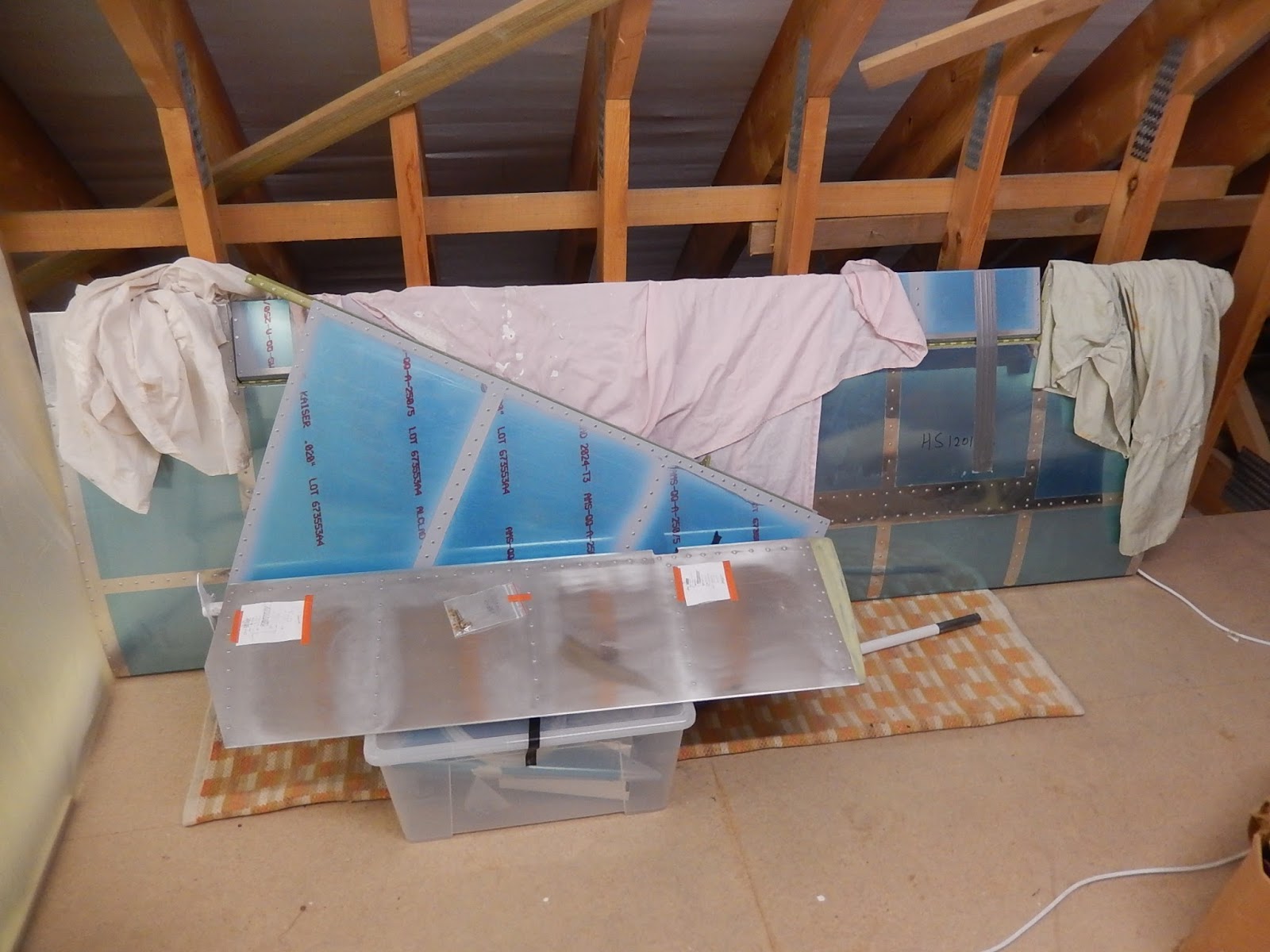
Since the inspection of the wing structure back in April, things have been a bit slow.  I have however managed to prepare all of the remaining parts - wing skins (just for the left wing), stall warn switch and landing light brackets etc.  I also built a mobile wing trestle to store the wings safely when not in work. 


Wings on the mobile trestle.

 
Some of the wing small parts being prepared and primed. The main skins had to be painted in the temporary paint shop (where my car normally lives!) as they're too big to get upstairs in the garage.
 
With all parts ready, it's now it's time to start assembling again.

This is the stall warn switch on the left wing leading edge. 
 
For the non-pilot readers:  Normally, airflow approaches from the front of the vane and pushes it down.  However, if the angle of attack is too high, airflow will come from below the vane and push it up, causing the micro-switch to close and sounding a horn to make me push the aircraft nose down, thereby hopefully preventing a stall.  Although it's been adjusted now according to the build manual, final adjustments may be required after flight testing if the activation speed isn't within limits..
 
Once the remaining wiring was installed through all of the ribs for the nav and strobe lights, the wing was turned over ready for the first bottom skin to be fitted.
 

Here's the first skin in place with alternate rivets and clecos.
 
The first skin all riveted in place. 

Close-up of the lower skin reinforcing plate - a modification that came about after the first aircraft went into service.  There are 62 rivets of 4 different types holding it in place!
 
Outboard bottom skin now in place and the nav light wiring hanging out of the last rib.  The wing-tip will go where the rivet gun in standing and it's made of 3 more skins and some complex angles.    There's also some fibreglass work involved - yuk!
 
The final centre skin is now fixed in place with a view of the stall switch access panel.  The wing is now in the temporary paint shop so I can prime the section of the inboard skin where the wing-walk doubler will be installed - the piece on the trestles to the left.    It's not obvious but under the cardboard  is the top inboard skin which also requires a small section priming for the aft end of the wing-walk.  I should have dealt with these bits of painting earlier but they got overlooked.  I'll get in right on the other wing!
 
The left wing now back the right way up  and in the build area, ready to start rolling the leading edge into place. 

A view inside the centre skin bays showing the stall warn switch and its access plate.  Before I close this section I want to add an extra static pipe for a future angle-of-attack indicator.  This requires a static port rivet to be fitted on the wing bottom skin a few inches behind the leading edge.
 
The 3 bottom skins all rolled and clipped around the ribs to form the wing leading edge.  This is quite awkward to get the holes all lined-up and not crease the skins.  In the foreground you can see the blue electrical connector which allows for quick removal of the wings.   The primed outside section of skin nearest to the camera is the bit I primed earlier prior to it having the wing-walk doubler fitted. I want all mating surfaces fully primed to prevent corrosion anywhere where moisture could get trapped.
 
The last part to deal with before the wing top skins are fitted is to install the two outboard flaperon hinges.    You can perhaps imagine some of the language when trying to get the bottom corner rivet installed through the rib when the two going through the skin and rear spar were already fitted!
 
 
And finally, just to prove it doesn't always go to plan, here is where a rivet didn't quite go all the way through a rib-to-aft-spar tab .  I didn't find it until I flipped the wing after the bottom skins were fitted.  Fortunately a bit of careful drilling got it safely removed and replaced without any damage!
 
 
There will be a bit of a gap again now before I can get on with the top skins - paying work and a holiday take priority. Once back underway in mid July I think it'll be just a few days to complete this wing.


Monday, 18 April 2016

Wing inspection

So just a short update as not a lot is happening at present - too much work and other distractions!

Finishing the first wing just required the last 6 ribs to be riveted in place.  Assembling the second wing structure went really quick - less than a day and then it was ready for Jerry to come for another inspection. 


Once the two wings were finished I also brought the HS down from the loft so Jerry could see it.

The HS looks pretty small compared to a wing!

As you may have spotted above, I've also re-arranged the back of the garage so I can store the wings along the left side.  This meant moving the work-bench to the back wall, so re-plumbing the compressor and moving the pillar drill.  Next job is to build the rolling wing stand (hence the timber on the floor) and then with one wing out of the way, I can start skinning the first one.

Saturday, 2 April 2016

More wings

I didn't have enough room upstairs to paint the rear spars (they're 11 feet long) so have created a temporary paint area in the garage.  This has meant moving the MG around a bit and I'm running out of floor space.  Mind you, seeing how some other builders cope, I can appreciate that I'm quite lucky to have such a generous build area.

 Here are the main spars in the temporary paint shop.  In the end, following advice from my inspector, and reviewing the opinions of the builders forum, I decided only to paint the areas I'd deburred and the un-treated rib attach brackets, as the major structural parts are anodised.

Another view of the temporary paint area - where the MG normally lives.  The curtaining is a 17 ft x 10 ft tarpaulin cut in half to make two 8.5 x 10 ft  pieces and hooked onto cup-hooks screwed into the ceiling.  This way, I can quickly take it down when not required.  When painting, I have large plastic sheets on the floor as well and a separate extractor fan which exhausts through the cat-flap!

Once I'd painted the rear spars, I could finally put the rear fuselage into storage.  

 Rear fuselage hanging from the garage ceiling.

Let's hope it's secure - otherwise it won't be just a damaged aircraft part to worry about!

So, back to aircraft building and time to start assembling the first wing.  There are several steps to complete before adding additional parts to the spars. 

Drill and tap the tie-down fittings on the main spar.  The blue cutting compound on the tap is called Boelube - apparently developed by Boeing.  

Finishing attachment of factory-fitted rib brackets and closing remaining holes in the spars.
  I brush-painted on the primer on these brackets.  For the 20-odd brackets that I had to complete and install, I spay-painted them first.  The major parts of the main spars are pre-assembled with all solid-riveting done at the factory.

My first assembly job was to install the rear ribs and brackets and the rear spar.  All very quick as I'd previously prepared all of the parts.  Here is the rear spar doubler and in-board flaperon hinge.  

The left wing on trestles with rear ribs complete and the forward ribs being installed.  Just the last 6 forward in-board ribs remaining to be done along with the forward stub-spar.  When this is done, I'll make the wing storage rack and then complete the right wing to the same level.  At that point, it'll be time for another inspection by Jerry before the wings can be skinned.

Looking inboard from the left wingtip through all of the aft rib lightening holes.  Time to worry if the holes aren't in line!

Left wing looking outboard with the remaining 6 forward ribs still to be fitted.

The position for the final 4 inboard forward ribs - much more closely spaced, as this is where you step onto the wing when getting into the aircraft.  The bronze bush on the left is where one of the wing securing pins go through to hold the wings together and to the fuselage centre-section. The pins allow the wings to be removed or installed in about 5 minutes.

Next week should see the left wing structure complete and work started on the rolling wing trestle.  After inspection, the wing will need to go onto the main construction table to allow the skins to be fitted and I'll also have the stall warn vane and strobe/landing lights to install.


Friday, 11 March 2016

Wings!

Having stored the fin, rudder and tail plane, I've started to prepare parts for the wings.
I'm working slightly out of sequence as I'm meant to deal with the spars first but that will mean re-arranging the garage.  The main spars are about 15 feet long as they overlap inside the fuselage, and the rear spars are 11 feet long, so I have to create a temporary painting tent as the spars won't go upstairs to the regular spray shop.

So, first job is to prepare the front stub spar and all of the aft spar hinge brackets for the flaperons.

 Here are the hinge parts and also the front stub spar and aft spar  fittings that engage into the fuselage.

Now all the parts primed and ready to start riveting parts together.

 End of the front stub spar with the doubler riveted in place.  Note the three countersink rivets in the fuselage tongue  - these are flush-riveted on both sides which was a pain as the specified rivets were slightly too long.  The empty holes in the face of the stub spar are where the front of the wing ribs will be attached.  The countersunk holes in the flanges are for the wing skins.  Doing the countersinking was awkward even with a machine countersink cage, as the depth still seemed to vary and I was quite worried about wrecking one of the spars!

Flaperon hinge brackets complete with bearings.  I wonder how you replace the bearings in service?  Unlike the rudder hinges which are bolted to the airframe,  these hinge brackets are riveted in place to the rear spar.  As with the stub spar, there are double-flush rivets adjacent to the bearing.

The next major items to prepare were the wing ribs.  Well over 30 hours spread over a couple of weeks sitting at the bench, cutting, filing, deburring, fluting and scuffing over 50 ribs prior to painting!    I have many cuts and grazes from sharp metal, plus raw fingers now from the scuffing with purple ScotchBright. 
There are two types of forward rib supplied, but after trimming tabs, flanges or both, you end with 6 different versions.  Same with the aft ribs as well - 2 standard types but you end up taking the aft flange of all right versions and have two differing left versions.  I guess it simplifies manufacturing for Vans but I think it's going to be pretty confusing when it comes to final assembly! 

A forward rib before and after fluting.  The curve is an unfortunate by-product of the manufacturing process when the edge flange is produced.  On the right side you can see the dimples between each hole which pulls the metal straight.  These are all done by hand using a special pair of pliers, but only once the deburring is complete (yes, I did one in the wrong order - big mistake!).

 Forward ribs on the painting bench.  


All of the forward ribs complete and stored below the bench ready for wing assembly.  The long pieces still covered in blue plastic are the spars for the flaperons.

The final 13 aft ribs ready to be painted.  There's more than full day's work preparing these.

Over the next week I have to paint the remaining aft ribs and create the temporary paint tent so I can paint the main and aft spars.  I also have to paint the top of the rear fuselage below the fin  - unfortunately overlooked during that stage,  before I can finally store the tail cone assembly.  After that, I'll have the space to pull the bench out from the wall and start wing assembly.  Exciting times ahead!

Saturday, 6 February 2016

A good start to the new year.

After the Christmas break and successful stage inspection, I've managed to make some good progress throughout January and have completed the first kit!

First job in the new year was to skin the horizontal stabiliser.  This was really quick - just over a day's work, as I'd already match-drilled, deburred and painted the skins, hinges and trailing edge ribs, so just loads of riveting.
 Here's the HS on the bench with the main skins fitted and waiting for the trailing edge ribs and hinges to be installed.

Now with the hinge halves clecoed ready for riveting

An exciting bit comes next - assemble the empennage with fin, rudder and HS to see if everything aligns and clearance of moving controls is OK.  The fin cap isn't installed at this point as it hits the garage ceiling!  First the fin and rudder are installed. This meant adjusting the previously chosen spacer washers in the rudder hinges as the fin didn't line up close enough to the top of the rudder.  A bit of juggling whilst still complying with the build manual requirements and everything lines up to my satisfaction.
  The paper with orange tape has the correct washers/bolt combination drawn on for each hinge so I don't have to work it out again on final assembly!

Next comes installation of the horizontal stabiliser, initially without the trim tabs fitted.

Now we move on to a part I'm not very keen on - trimming fibreglass.  Previously I'd trimmed the fin and rudder caps to size.  This time it's to make the two halves of the tail cone fairing. You're supplied with 2 moulded pieces - each like 1/2 an egg and with very feint scribe lines to trim to.  I did the initial trimming using a fine high speed cutting disc in an air grinder - a bit like a Dremmel. Once close to size, I then had a lot of fitting/removing/filing and sanding to get a satisfactory fit.  Only then can I start to join the two halves together.

Here are the two pieces held in place with clamps whilst the joining plates are aligned and drilled.  The rudder is offset to the left which makes the cone appear distorted.  Also, the slot for the trim tab actuating arm still has to be cut-out.

Another view of the joining plates.  These will eventually be riveted to the inside surface of the lower half of the fairing and anchor nuts fitted on the top half of the plates.

Anchor nuts have to be fitted to the skin around the rear bulkhead to hold the fairing halves to the airframe. It's an awkward job as they're on the inner face of a curved skin, are dimpled and it's very difficult to get a drill in to match some of the holes to the skin.  

Moving on, I have to assemble the trim tab motor and actuator assembly, and for the first time, a bit of my own type of work, aircraft wiring to do!  (well I did put the nav antenna cable in as well).
The motor on it's base and wired to mate with the cable already installed in the fuselage cone.  Note the loom string and not tyraps for those who have a clue.  Perhaps a bit old-fashioned, but I hate cutting my hands on sharp tyrap stubs!  The split pins are temporarily fitted as the nuts won't be finally tightened until the assembly is finally installed and rigged.

The complete trim assembly.  I've painted the actuator arm in white epoxy as it will be visible where it protrudes through the tail cone fairing and attaches to the trim tab.

There is one small outstanding item, which is to fit and adjust the trim assembly to the bulkhead and HS, but I'm short of one 1/4" nylon bush and don't want to pay huge freight for such a small item, so will wait to consolidate it with more parts later. The small amount of work for this item can be done during final assembly.

I had to remove the refit the HS 3 times to complete the fibreglass work and fit all of the fuselage anchor nuts. Finally, I put it all back together again for one final interference check.  
All parts assembled, and end of empennage construction.  All surfaces move without interfering and all the gaps are pretty consistent.

Wow!  It actually looks like the back end of a real aircraft.  I have to say that it does generate a real sense of satisfaction to have completed this first major part, in just over 5 months. Now I move onto the wings and I reckon they will take me to around the end of June, so another 5 months.  Before I can lay out the wing main spars, I need to dismantle and store all of the empennage so I can get the construction bench into the middle of the garage (the wings are longer than the bench and it fits into a recess currently). 

The horizontal stabiliser, fin and rudder have gone upstairs in the garage.


The fuselage cone is going to hang from the ceiling above my MGA.  I wont need these parts again now until the fuselage centre-section is complete and needs to be joined to aft fuselage cone., so probably around the end of the year.

Wednesday, 30 December 2015

A bit of Chrismas cheer.

Welcome to my last post of 2015.  Although it's the Christmas holidays and I didn't foresee much progress, I got in a few hours before Christmas Day and a few more since then, so I have been able to get the tail cone completed and my next stage inspection passed by Jerry.  As I don't have a target for completion (it's meant to be a fun hobby after all), I'm pretty pleased with progress so far.

First task since the least visit was competing preparation and painting of the remaining skins and top rib.  

Fitting anchor nuts to the fin attachment rib which will go on the top tail cone skin

After the upper side skins were pinned in place, it's time to start out-fitting the tail cone. There's not a great deal in the rear - control cables for rudder and elevator, wiring for the electric trim, nav antenna cables and static pipework.

Strings fitted to pull-through the elevator and rudder cables (in about a year!).  Also installed the pitch trim electric cable loom and the static port pipes to the ADAHRS. 

You can just make out the inside of the left static port.

This is the right static port from the outside - it's a pop rivet with an over-sized head and the mandrel pushed out. 

Now the final top skin is pinned in place, all holes match-drilled and then the skin removed again to deburr the holes.  Finally, it's back on again and ready for riveting.

Top skin clecoed in place and ready to rivet. 

You can see the remaining pins securing the skins to the fuselage frames.

The completed tail cone ready for inspection.

A top view of the fin attachment rib.  The skin below the rib has been primed to prevent corrosion.  The antenna connector is for the nav antenna in the fin cap, and allows for easy installation or removal of the fin.

Inside the completed tail cone.

My next job is to skin the horizontal stabiliser (HS).  The skins are already prepped and painted.  Moving on, it'll be a trial-fit of the fin/rudder and HS to the tail cone.  At this stage, it will look like the complete rear-end to an aircraft!  Once this is done, I have to deal with the trim motor mountings and then make the tail cone fibreglass fairings fit (apparently a bit long-winded to get good alignment with all of the securing brackets) .  I reckon this will take me to the end of January, and then it'll be time to start on the wings.

To all readers - thanks for visiting and my best wishes for a Happy New Year.