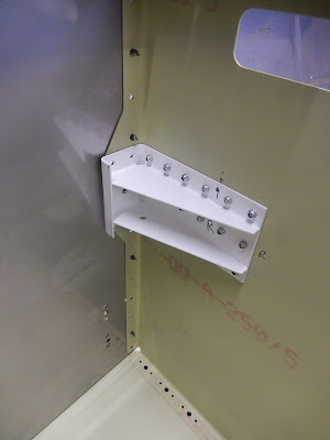
First job was to fit the autopilot roll servo brackets at the back of the baggage bay floor.
Here are the servo brackets attached to the aft floor bulkhead. The servo control operating arm will move the flaperons. The servo motor won't get installed until the tail cone is attached and all drilling etc is complete.
Now I've moved on to building the forward lower fuselage section on the bench. This part comprises the lower firewall (stainless steel and very sharp!), engine/undercarriage mounts, forward floor (where your feet sit on the pedals) and the centre tunnel below the throttle.
This picture shows the right-hand lower engine/undercarriage mount fixing inside the tunnel. Below the engine mount on the floor you can see a set of holes for anchor nuts - this is where the bottom of the nose landing gear will be bolted on from underneath the fuselage.
The assembled firewall with both lower engine mounts, tunnel sides, forward floor and fuselage lower side skins. The hole on the left side of the tunnel floor is for the transponder antenna.
The lower firewall with the lower fuselage side skins cleco'd in place ready for riveting.
Now I've temporarily attached the firewall structure to the centre tub.
Looking forward into the foot wells at the inside of the firewall. When you're seated, one foot goes each side of the rib running forwards across each foot well floor panel.
A final view of the riveted structure with the additional engine cowling brackets on the bottom flange of the firewall. The is a diagonal stiffener to add on the right side of the firewall (left side of the picture. The matrix of holes on the opposite side is for the heater to let air into the cockpit. On top of the firewall is the temporarily cleco'd firewall shelf where the rudder pedal support brackets will be fitted in the next step.
Having completed the lower fuselage and ready for inspection, I've moved on the preparing the main fuselage side skins and other parts.
To start, you have to make two longerons from 7-feet lengths of thick 1" extruded aluminium angle. I was dreading this as there are loads of discussions on the Vans forum about the challenges this step creates. You have to open the 90 degree angle to 95.4 degrees over the first 12 inches, plus add a 2.7 degree twist, then create an accurate curve over about 40 inches for the cockpit sidewall. The picture shows the left longeron almost completed after much hassle!
Over the next week or two, I'm going to prepare all of the remaining fuselage parts so I can have a large assembly session and then it's into fitting out plumbing and wiring!


No comments:
Post a Comment