First job after the fuselage-joining inspection was to prepare all of the undercarriage parts - the main legs, wheel fairing brackets, nose wheel fork etc. Unfortunately I didn't take any pictures of the pre-installed parts!
Here's the first part installed - the left main undercarriage leg together with axle and fairing bracket. Note to self: Next time, put the brake caliper on BEFORE fitting the fairing bracket! Installing and tightening the undercarriage bolts is a bit of a headache and I needed to drill a couple of holes in the belly skin, which are listed in an old service bulletin which weren't already present in my kit. These holes are needed to get a 1/4" drive extension bar and socket onto the bolt heads.
Here's the right main leg with the brake caliper correctly installed.
Next it's time for the nose leg and fork to be fitted. Although my kit came with an un-used standard fork, I've bought the up-rated nose fork as there have been many reports of the original design cracking. The bolt with a stack of washers is where the tow bar attaches for ground handling. The two black fixings at the top of the leg onto the firewall are 3/16" skin pins - being used as temporary fixings until the lower engine mount is bolted on to this location. These holes will eventually be drilled out to 3/8".
The nose-wheel is free-castoring - there is no directly-coupled steering, so you change direction by use of rudder and differential brakes.
So onto the wheels. I chose the paint the wheel halves as they'll be hidden inside fairings and open to corrosion if the aircraft eventually ends up living outside. I used a Lazy Susan (used for cake decorating) to allow the wheels to be rotated when painting and this allowed for a decent finish.
I have no prior experience of assembling split-rim aircraft wheels with tubed tyres so it took a bit of reading the manual and fiddling to get the valve stem in the right place and not pinch the tubes, but finally they all went together OK. What I also learnt was that I needed some new hex bits in sockets so I could correctly torque the bolts.
So it's finally on it's wheels!
I just had to take the aircraft outside for it's first view of daylight!
So moving on, I've continued with the electrical and avionics systems in readiness to fit the instrument panel. This is needed before the canopy can be installed.
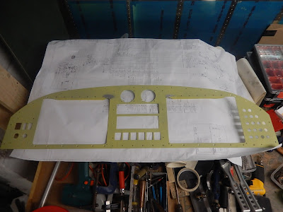
I completed the instrument panel itself by riveting stiffeners above each main screen cut-out, added some anchor nuts and drilled all of the circuit breaker holes. Now it's primed and ready for the carbon-fibre film to be fitted.
More work proceeding on wiring. Intercom, both PFDs (pilot and co-pilot main screens), autopilot, transponder and radio are now finished. The main items to complete are the circuit breakers, switches and the engine interface unit (top left on the bulkhead).
A plan view of the part-completed avionics bay wiring. Everything starts from the centre where the main aircraft harness comes up through the avionics bay shelf.
This is the Garmin GEA24 - the interface between the engine/airframe sensors and the EFIS screens. Once the wiring is completed it'll be clipped to the bulkhead to allow the top cover to be installed without chafing.
This is some of the electrical wiring in the engine bay - for the battery and start contactors, and the ammeter shunt. The shunt is normally inside the Vans switch/fuse panel but I'm not using that. Also in the picture are the manifold pressure sensor (top centre) and fuel pressure sensor on the right of the picture with the yellow cap on the pipe fitting.
I've also temporarily installed the battery - merely to add some weight to the nose now the aircraft is on it's wheels. Without this it wanted tip onto its tail!
I took some time away from wiring to finish the braking system by installing the main leg brake pipes and attaching the rigid plastic pipes from the park-brake valve to the undercarriage brackets in the centre section. I've chosen to use after-market braided flexible hoses on the legs instead of the Vans-specified aluminium pipes as this allows for removal of the brake calipers without needing to bend rigid pipes.
Finally I completed the internal controls for the flaperons in readiness to trial-fit the wings. With the wings installed, the flaperon control arms can be match-drilled whilst the controls are locked in a rigging position. Hopefully I can get the aircraft out of the garage again in the next week and complete this step.
This view is looking down and aft on top of the flaperon controls - the white tubes exit the fuselage sides and engage with the flaperons on the trailing edge of the wings. The green rods connect to the mixer between the seats which in turn connects to the pilots' control sticks.
I wasn't happy that the two bolts on the end of the green push-rods were in alignment when the controls were in neutral so took the lot out and re-measured/adjusted the rod ends until everything was aligned accurately. It's difficult to get the price dimension stated in the build manual and surprising how a quarter turn either way on opposite rods can have a dramatic effect.
I'm not proceeding as quick as expected but hopefully will complete the electrics/avionics in the next couple of weeks and start on the canopy.


No comments:
Post a Comment