Saturday, 25 February 2017

Seat structure

It's been a productive week - making good progress on the main fuselage.

To begin this session, I completed assembly of the baggage area floor structure - adding the bearing supports for the flaperon controls.

Close-up of the flaperon bearings and the support channel in the centre.  This area is the subject of a service bulletin from Vans where the support channel is known to crack at rivet holes after a few hundred hours in service.  My kit has the improved system with extruded supports for the channel between the bearings.

A view of the completed baggage bay floor structure.

So now on to the cockpit floor and seat structures.  Unfortunately I didn't take many intermediate photos - just got on assembling the 70 pieces that I'd previously prepared.  You have to follow the instructions very carefully in the right order or you can't get access to put in some of the rivets and also so you don't dimple the wrong holes!.  

Looking aft from the front of the right (passenger) seat. The bracket in the centre of the middle ribs is for fixing the crotch strap of the passenger seat belt, and the small brackets to the right are for a control pulley. 

 This is looking down on the same area shown above.

This is the left seat structure looking aft and showing the flaperon mixer which is protruding into the tunnel between the seats.  It'll be interesting to see this come together as I can't yet see how it works!  It's only moves about +/- 10 degrees fore-aft.  To the right of the mixer (left-side in the aircraft) you can see a thick doubler inside the second vertical rib.  This is an extra part needed if installing an autopilot so I'm taking advantage of doing it now whilst everything is more accessible.

 Looking down and forward on the pilot's seat pan with the flaperon mixer on the right.

The two seat structures just placed in front of the centre section where they'll be riveted on the next build session.  It'll start getting two-handed to move about once these are fitted.   At the rear of each seat pan you might spot some small lugs sticking up at 45 degrees.  These are where the seat belt lap-straps are installed. The channel between the two taller vertical frames in the centre is where the main undercarriage legs fit. 

Final view from this session, looking down on the two seat structures resting against the centre section.   The sections of hinge running across the seat pan are to hold the bottom of the backrest - two positions allowing for adjustment for taller/shorter pilots.   I did make a mistake here - I had the end lug and space the wrong way round on all four pieces of hinge so had to re-make them.  Fortunately I had some spare hinge from correcting a previous error on the stabilator trim tab.  

I also prepared a few other parts today so I can make another full day of assembly.  Then it's back to a several days of prep again but that'll have to wait as I'm away for work and holidays for most of March.

Monday, 20 February 2017

Fuselage underway

Fortunately the minor operation on my right knee went very well, so much so that I didn't need crutches at all and am walking almost totally normally after just 3 weeks.  So it's time to get back in the garage, with the added benefit of some warmer weather.

As mentioned in my previous post, the aim now is to do much more preparation each time, so  reducing wasted paint and to give a greater time on assembly.  With this in mind I prepared about 70 parts of the centre fuselage - going forward through the build manual to try and catch all of the parts I'd need for a large assembly step.  Rather tedious sitting there filing and deburring for days on end but it's a means to an end as they say.

A large selection of fuselage parts painted and ready for assembly, sitting on top pf the main belly skin.

The first assembly job is to fit some corner pieces to the centre section bulkhead, followed by installing the aft bulkhead and side supports.  Included at this stage in the manual is bolting-in of two nylon guide blocks.  I've just put them in place loosely so they can be removed when the interior is painted before fitting out of systems.


 The centre section with the aft bulkhead installed.  Lots of aching hands and arms after hand-squeezing all of the solid 1/8th rivets.

End view of the centre section (I need to touch in some of the paint).  The main undercarriage legs will, bolt to the underside of the large machined U-section between the two bulkeads.   The wing-pin bushes are still masked off and will stay like that until the interior has been painted.

Fitting the baggage bay floor panels to the centre-section aft bulkhead.  Some of the end rivets are particularly awkward and I ended up using a pneumatic gun and backing block for a couple where squeezers wouldn't fit.   Haven't done much of that type of riveting since I was an apprentice!

 Baggage floor installation complete.  The hole of on the right floor panel is for the fuel tank outlet - the tank occupies the right side behind the seats and the baggage area is on the left.

This picture shows the floor ribs installed below the baggage bay floor, and the next parts (rear spar carry-through, flaperon bearing blocks and additional floor ribs) ready to fit.   The two semi-circular rivet patterns are for the rear wing-spar locating point.

 End view of the rear spar carry-through.  The 'pocket' is where the tab on the wing rear spar will engage in the fuselage.  There's no bolt to fix it - the only wing fastening will be two large pins through the main spars and the centre-section bushings shown above, to allow for quick wing removal/installation.

 A view of the underside of the baggage bay floor showing the ribs installed.

Finally a view of the front side of the centre section.  The seat structures will be attached here in the next stage of assembly which hopefully will continue very soon.


Saturday, 14 January 2017

Completed flaperons

Welcome back after the Xmas break, where little happened in the man-cave.  Time to crack-on and see if I can get this aircraft flying before next Christmas!

I spent a few hours before the Xmas break completing the flaperons which were awaiting some additional rivets due to a design change.  I managed to pick these and some other spare parts up (along with the mandatory baseball cap and logo'd fleece!) from the Vans factory during a fortuitous visit to the US west coast in early December.  The factory is very much like an English cottage industry affair - very similar to Morgan Cars if you've had the chance to go there.

Jerry popped in for the obligatory stage inspection just after Christmas - many thanks, and then with help from Sam, we have now bolted the completed flaperons to the wings and put them in the storage rack.

 Here's the left flaperon gaining the final trailing edge skins.

 Another view of the left flaperon from the inboard end showing the hinge and actuating tab.

Finally assembling the left flaperon to the left wing.  The wing is upside-down for this so I can access the hinge bolts.  

This is the left wing flaperon inboard hinge.  Getting the two spacer washers in either side of the bearing is a real fiddle.  Anyway everything is torqued together for good - shouldn't need to come apart again until painting on completion of flight testing! 

 A view along he completed wing/flaperon assembly.

Both wings back on the rack with flaperons fitted. 

Next stage is to start on the main fuselage/cockpit assembly.  This is the last major structure to build but also the most complex, and it has all of the avionics, wiring and flying controls to fit.  The first part is the centre-section bulkhead structure which supports the wings and main undercarriage.

 This view is of the main fuselage rear lower skin and centre section frame cleco'd together so I can match-drill the aft bulkhead (the piece with all of the clamps holding it in place).  73 holes to drill in pretty thick metal took quite a while and needed several sharp drills.

Same as above but viewed from the opposite side.  We're looking at the left side of the cockpit so the skin to the right in the picture will be under the baggage bay, behind the seats.

Centre-section aft bulkhead with the belly skin removed and all new holes cleco'd.  

I then spent quite a few hours at the bench preparing floor panels, multiple brackets etc. for painting and will get as many parts ready before starting assembly.  This way I hope to save waste on paint and have a better time assembling large sections at one go.  I'm having an op on my right knee in a few weeks (I had my left one done last July) so would like to get the main centre section structure completed before that as I'll be immobile or at least unable to do much else for most of February.  At least having the knee op now means it's done during the coldest time of the year when I least want to be in the garage!

Friday, 25 November 2016

Wing inspection and flaperons

Jerry popped down last week and my completed wings were inspected and signed off without issue, so that's a relief.  Now to move on to the flaperons.  However, before I start I need to make the garage more usable for the winter.  Last year it was far too cold so I was wrapped up like an Eskimo and had the heater running full blast and it made only a marginal difference. I decided to insulate at least the garage door which is just thin sheet steel.  I've stuck on a 25mm layer of Celotex and filled any gaps in the frame with expanding foam. The difference is pretty remarkable - the heater will actually cycle on its thermostat!  Perhaps I should try some roof insulation as well.


With the garage a bit more bearable, it's on with the flaperons. 

To start with, there is some trial assembly of the nose ribs, counterbalance weight (a four-foot length of stainless steel tube) and the outboard leading-edge skin.  This is to allow the holes in the counterbalance to be marked and match-drilled to the pre-punched holes in the leading edge skin and nose ribs.  Worried about wrecking the skin (it's only 0.015" thick) by match-drilling in-situ, I chose just to mark the holes with a spring centre-punch and then drill the holes using the pillar drill and a vee block, and this worked well.  No picture unfortunately!

Here's the outboard end of the left flaperon temporarily assembled after match-drilling. 

A view of the same flaperon showing the inboard end of the counterbalance.

Next job is to prep the parts.  There are 24 trailing edge ribs, 2 main spars and 10 skins as well as all of the small brackets.  Time consuming is an understatement - this prep is probably the least interesting yet most labour-intensive part of building this kit. 


 4 trailing edge skins prep'd and painted.

 All of the small parts on the paint table.  You can see the counterbalance tubes hanging down from the ceiling.

One set of small parts and a section of the spar for one flaperon.

Once painting was complete I could move on with assembly.  I started by fitting all of the small brackets and nose ribs to the front face of the spars

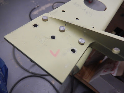
 This is the inboard end of the left flaperon.  It's very tight to get a rivet set onto the end of the solid rivets due to the machined radius in the plate and I need to tidy the paint where I've scuffed it!  The tab where the red L is marked is the interface to the moving control in the fuselage and will make the flaperon rotate around the pivot hole.   

 Another view of the inboard end with the nose rib installed and the remaining tab holes now filled as there's a trailing edge rib also fitted.  The gap between the nose rib and actuating tab is precisely 0.5" and will have the inboard of three pivot bearings installed.

This is one of the other two pivot-bearing mounts.  

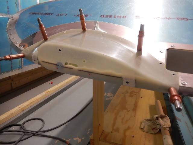
 The outboard end of the completed right flaperon structure ready to be skinned.  You can see the outboard bearing bracket behind the counterbalance tube.  I finished the left one to the same stage before moving on.

 Firstly the trailing edge skins are fitted and then the outboard leading edge as shown here.

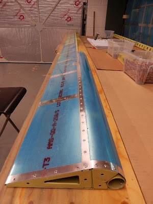
 You can get an idea of the length of the flaperon here - they are just about 11 feet long!


This is the final view of where I'm up to - the right flaperon with trailing edge skins and the outboard leading edge complete.  Actually there has been a recent change in the plans so I need some additional special rivets for the last rib hole in the trailing edge.  These can wait until until I have an order together for other parts.


Tuesday, 1 November 2016

Both wings completed.

A bit sooner than expected (nothing before has gone to plan!), I've finally completed the wings.  I do still have the flaperons to do but nevertheless it does feel like a milestone has been reached.

The outstanding items were the right wingtip structure and then completing the nav light fairings and wiring on both wings.

 I started off with the upper and lower tip skins and the hand-hold frame - very straightforward.

 Next is the aft end rib.  It's a pre-formed U-section and simple to install.

 The forward tip rib it much more awkward.  It has complex curves and a twist and needs fluting on the top and bottom edges to make it follow the correct profile.  

This is the finally formed forward tip rib installed.    In reality the fit looks like a smoother curve than in the photo.

 Now the bottom skin goes on.  Loads of small tabs along the bottom inboard edge have to be bent at different angles from 18 to 136 degrees.  In the end it worked out better than the left wing.  I cut the nav light access hole whilst the skin was still on the bench.

 A view of the completed wing-tip from the trailing edge looking forwards.

 A bit of the design that I don't really like.  There is a step in the leading edge profile where tip rib and skins don't really line up.  It is in accordance with the plans but nonetheless I'm going to smooth this section out with some epoxy/flox mix when I deal with the nav light fairings.

 This is the trimmed nav light fairing secured for match-drilling.  I failed to record any of this for the left wing!

 Another view of the cut-out to get access to the nav light wiring and the holes all drilled for the fairing attachment.  The two holes marked in red were meant to be left vacant when riveting the skin.  I still managed to put a rivet in one and had to drill it out again! I'll prime this area before fitting the fairing.

 Here the wing has been up-turned and the fairing temporarily attached with epoxy/flox mix inside, below the black line to ensure a snug fit the the outboard tip rib.  Flox is fine shredded cotton fibres that are mixed into an epoxy resin to make it stiff so it will act as a filler without running out.  The wing tip has car wax on it to act as a release agent so I can get the fairing off again.  You can see a blob of blutack through the fairing - this is to keep this area clear for a nut which secures the nav light assembly.

 Inside the fairing once the epoxy/flox mix has set.  I sanded the excess epoxy off using a rotary sander to save some weight!

 Finally, the fairing is installed and riveted.  The dark edge is the PRC between the fairing and skin (Fuel tank sealant as called out in the plans).  I really dislike PRC - it stinks, gets everywhere and is difficult to remove!  I'd previously left this stage on the left wing until I could mix one batch of sealant for both wings.   On the outside of the fairing is the mounting bracket for the nav/strobe light and the completed wiring disconnect.

Two completed wings on the stand and with the nav/strobe lights installed.  You might be able to see by the uppermost rivet where I blended-in the step in the leading edge.  Time to move onto something else after 10 months of just wings!

 A view of the completed wings from the inboard (root) end showing the electrical connectors.  The pipe sticking out of the left wing is for the angle of attack (AOA) sensor.

 Before moving on with more building, I needed to update the plans.  Loads of revisions have been issued, although fortunately none affecting anything I've done so far.    I will need to buy some improved parts to replace existing but unused bits for the fuselage.  Hopefully not too much expense but best to start with the aircraft having the most recent build standard and product improvements when it first flies.

Here's the next step - parts for the two flaperons.  Whilst these are in build, I have an inspection scheduled for the completed wings.  Hopefully nothing shows up that I've got wrong!