Friday, 21 April 2017

Firewall and longerons

A brief update on this week's activities.  Not too much visible progress but the main lower fuselage is now ready for its stage inspection.

First job was to fit the autopilot roll servo brackets at the back of the baggage bay floor.

 Here are the servo brackets attached to the aft floor bulkhead.  The servo control operating arm will move the flaperons.  The servo motor won't get installed until the tail cone is attached and all drilling etc is complete.

Now I've moved on to building the forward lower fuselage section on the bench.  This part comprises the lower firewall (stainless steel and very sharp!), engine/undercarriage mounts, forward floor (where your feet sit on the pedals) and the centre tunnel below the throttle. 

This picture shows the right-hand lower engine/undercarriage mount fixing inside the tunnel. Below the engine mount on the floor you can see a set of holes for anchor nuts - this is where the bottom of the nose landing gear will be bolted on from underneath the fuselage.

The assembled firewall with both lower engine mounts, tunnel sides, forward floor and fuselage lower side skins.  The hole on the left side of the tunnel floor is for the transponder antenna.

 The lower firewall with the lower fuselage side skins cleco'd in place ready for riveting.

 Now I've temporarily attached the firewall structure to the centre tub.

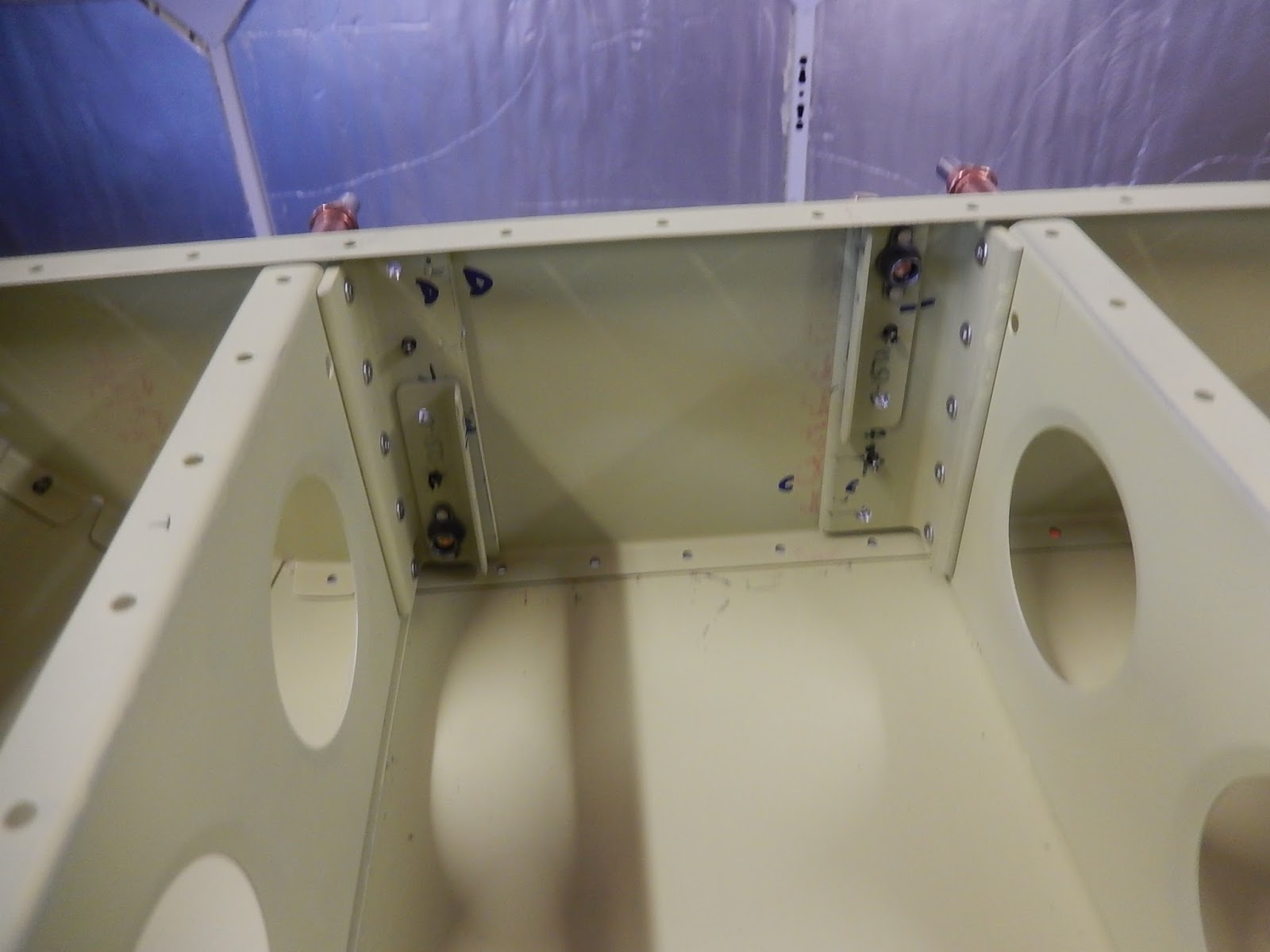
 Looking forward into the foot wells at the inside of the firewall.  When you're seated, one foot goes each side of the rib running forwards across each foot well floor panel.

A final view of the riveted structure with the additional engine cowling brackets on the bottom flange of the firewall.  The is a diagonal stiffener to add on the right side of the firewall (left side of the picture.  The matrix of holes on the opposite side is for the heater to let air into the cockpit.  On top of the firewall is the temporarily cleco'd firewall shelf where the rudder pedal support brackets will be fitted in the next step.

Having completed the lower fuselage and ready for inspection, I've moved on the preparing the main fuselage side skins and other parts. 


 To start, you have to make two longerons from 7-feet lengths of thick 1" extruded aluminium angle.  I was dreading this as there are loads of discussions on the Vans forum about the challenges this step creates.  You have to open the 90 degree angle to 95.4 degrees over the first 12 inches, plus add a 2.7 degree twist, then create an accurate curve over about 40 inches for the cockpit sidewall.  The picture shows the left longeron almost completed after much hassle!

Over the next week or two, I'm going to prepare all of the remaining fuselage parts so I can have a large assembly session and then it's into fitting out plumbing and wiring!

Thursday, 13 April 2017

More centre fuselage.

Since returning from holiday I've continued making good progress on the main fuselage structure, with probably the most concerted period of activity in the last 12 months. 


Control tube installed onto the 2 bearing supports.  The deliberate mistake in this picture is that both bolts should have the heads outboard and the one on the right is facing the wrong way.  I corrected this before moving on!  Once the aircraft skin is fitted, it won't be possible to get this tube out again.  Also if a bearing in the support bracket needs changing, the whole bearing bracket will need to be drilled off and removed from the aircraft - a bit of a dockyard job!
a 
Looking rearwards through the hole in the seat front bulkhead (below the pilot's knees) where the pilot's control stick will fit onto the control tube.

Lots of parts preparation for the lower fuselage side skins and the fuselage step floor.  

 
The fuselage structure upside-down and showing the left-hand lower side skins.  Lot's of individual overlapping sections are used to take up the complex curve.  It's a bit like an Armadillo's armour!  On the right you can see the step floor ribs.

With both lower side skin sections in place, it's time to fit the main belly skin.  This is probably the largest individual skin in the kit.   I didn't count but I think there must be about 500 rivets holding this on and it took several hours and aching hands putting in and removing cleco pins!

Looking down on the belly skin (top of the picture is to the rear of the aircraft) showing the access panels for fitting the main undercarriage, rigging controls etc.  The yellow triangular plates are additional doublers to help spread the load between the skin, floor ribs and centre section bulkheads.  The blue plastic was removed and the skin painted underneath the doublers before they were finally riveted in place.  Left of centre you can see a large round hole - this is for the VHF antenna connector.

With the belly skin installed, the fuselage is turned the right way up and work commences on the step floor bulkhead and the step reinforcing angles.  Here the step anchor nuts and mounting angles are being installed.

The steps need to be leveled before drilling the final hole for the top mounting bolt.  Here I've checked the fuselage is level on the trestles and then set the step as close the level as I can manage - 0.3 degrees.  I can't get it dead-on as the top of the step arm would stick above the bulkhead but it's close enough for me.
If you've noticed, the steps are in front of the seats, meaning you access the cockpit by climbing onto the wing from the front - directly behind the propeller, so not something to do with the engine running!

Both steps fully installed.  They now come off for painting and to make continued building easier, and won't get fitted for good until we have the aircraft in the hangar at the airfield for finally assembly prior to flight.  My kit was delivered with the original step design, which has subsequently been updated to improve resistance to cracking at some welds (possibly due to heavier pilots than I).  The change to the step design doesn't affect the mounting points (although the bolts are different lengths which briefly confused me as I'm working to the latest drawings which call out shorter bolts and they weren't long enough!).  I'm going to stick with the steps I've got initially and just keep a good eye on them.  

With the step structures completed, the step floor panels can be fitted.  Daughter's boyfriend James got involved here, final-reaming #30 all of the holes and pulling the rivets. With the floor down, the nylon bushes which protect wiring, control cables and pipework from chafing on the metal structure are installed into the bulkheads.  In this view you can also see the pilot's and co-pilot's control stick connections to the control tube.

Another small bracket to install at this stage - the electric fuel-pump mount, which is in the centre tunnel below the baggage bay floor.  There's also a mechanical pump on the Rotax engine.

I needed some help to fit the six studs into the cockpit centre tunnel.  These will be used to mount nylon blocks which secure the fuel and brake pipes.  James drew the short straw and is fitting the nuts to the studs above his head whilst yours truly holds the screwdriver!

I've started preparing all of the parts for the remaining forward lower fuselage section (the floor below the rudder pedals) and the engine firewall, so hopefully I'll have this section completed and ready for a stage inspection in the coming week.


Saturday, 1 April 2017

Main fuselage continued.

Back from holiday and I started by preparing another load of fuselage parts in anticipation of a big assembly session.

To start with, I installed the wing spar box closure pieces and fitted the wing-spar rollers which aid quick wing removal and installation.

 This is the left side of the spar box.  The cockpit roll bar will fit on top of the box-pillar.  The taped-off holes are the large bushes where the wing securing pins are fitted.  I masked them to keep then free of paint when originally priming the parts and will leave them masked until the cockpit has been finally painted grey.

This picture shows the left wing-spar roller.  There is an aluminium tubular spacer inside the roller to ensure it doesn't stop rotating when the securing bolt is tightened.  In this view you can also clearly see the brackets which hold the seat-belt lap-straps for both occupants.

A view from the right side of the fuselage through the spar box showing both rollers and the spar guide blocks.  Note that the rollers fit in opposite directions.

Next job is to assemble to control column bulkhead with the front stub-spar pockets, control column bearing brackets etc.  I didn't take any stage pictures so here is the finished product!

Aft side of the left wing front stub-spar pocket showing the reinforcing structure. 

Looking into the pocket for the left wing front stub-spar.  In this view you can see the additional bracing structure on the forward face of the bulkhead.

Final view of the stub-spar pocket reinforcing, looking aft on the left side on the 
fuselage.  The holes with red edges are where rivets mustn't be installed at this stage,
so it's my way of making sure I don't put them in by mistake!

Left-side control tube bearing bracket.  The bearing bracket is assembled before being riveted to the bulkhead.  Trying to flush-rivet the four rivets around the bearing was a challenge and took several attempts.  I do wonder how you'd change a worn bearing as a maintenance action in the future - quite a lot of dismantling would be required.
The two horns on the plate in the centre of the bearing bracket are the elevator control limit stops.

 
This is the reinforcing plate around the control column aperture.

Looking down on the seat pans with the control bulkhead cleco'd in place ready for riveting.  You can see how many anchor nuts are needed for removable access panels.  I still have a few hundred in the parts bin! 

 A view on the control bulkhead looking aft .  The next job is riveting this to the seat base ribs before adding six more ribs and the cockpit floor step.

Final view for this section, with a view that covers the front and rear stub-spar pockets and the main spar box.    If you've followed what's gone on so far, you'll realise that the left side of the picture is the front of the aircraft.  Not long now before I can sit in the seat and make aeroplane noises and push a control column around even if it won't actually look like an aircraft!
Having worked on Cessnas and Pipers from the last 25 years, the RV12 cockpit floor seems to be a much more complex structure (perhaps for crash-worthiness?) even if the materials seem much thinner.


Saturday, 25 February 2017

Seat structure

It's been a productive week - making good progress on the main fuselage.

To begin this session, I completed assembly of the baggage area floor structure - adding the bearing supports for the flaperon controls.

Close-up of the flaperon bearings and the support channel in the centre.  This area is the subject of a service bulletin from Vans where the support channel is known to crack at rivet holes after a few hundred hours in service.  My kit has the improved system with extruded supports for the channel between the bearings.

A view of the completed baggage bay floor structure.

So now on to the cockpit floor and seat structures.  Unfortunately I didn't take many intermediate photos - just got on assembling the 70 pieces that I'd previously prepared.  You have to follow the instructions very carefully in the right order or you can't get access to put in some of the rivets and also so you don't dimple the wrong holes!.  

Looking aft from the front of the right (passenger) seat. The bracket in the centre of the middle ribs is for fixing the crotch strap of the passenger seat belt, and the small brackets to the right are for a control pulley. 

 This is looking down on the same area shown above.

This is the left seat structure looking aft and showing the flaperon mixer which is protruding into the tunnel between the seats.  It'll be interesting to see this come together as I can't yet see how it works!  It's only moves about +/- 10 degrees fore-aft.  To the right of the mixer (left-side in the aircraft) you can see a thick doubler inside the second vertical rib.  This is an extra part needed if installing an autopilot so I'm taking advantage of doing it now whilst everything is more accessible.

 Looking down and forward on the pilot's seat pan with the flaperon mixer on the right.

The two seat structures just placed in front of the centre section where they'll be riveted on the next build session.  It'll start getting two-handed to move about once these are fitted.   At the rear of each seat pan you might spot some small lugs sticking up at 45 degrees.  These are where the seat belt lap-straps are installed. The channel between the two taller vertical frames in the centre is where the main undercarriage legs fit. 

Final view from this session, looking down on the two seat structures resting against the centre section.   The sections of hinge running across the seat pan are to hold the bottom of the backrest - two positions allowing for adjustment for taller/shorter pilots.   I did make a mistake here - I had the end lug and space the wrong way round on all four pieces of hinge so had to re-make them.  Fortunately I had some spare hinge from correcting a previous error on the stabilator trim tab.  

I also prepared a few other parts today so I can make another full day of assembly.  Then it's back to a several days of prep again but that'll have to wait as I'm away for work and holidays for most of March.

Monday, 20 February 2017

Fuselage underway

Fortunately the minor operation on my right knee went very well, so much so that I didn't need crutches at all and am walking almost totally normally after just 3 weeks.  So it's time to get back in the garage, with the added benefit of some warmer weather.

As mentioned in my previous post, the aim now is to do much more preparation each time, so  reducing wasted paint and to give a greater time on assembly.  With this in mind I prepared about 70 parts of the centre fuselage - going forward through the build manual to try and catch all of the parts I'd need for a large assembly step.  Rather tedious sitting there filing and deburring for days on end but it's a means to an end as they say.

A large selection of fuselage parts painted and ready for assembly, sitting on top pf the main belly skin.

The first assembly job is to fit some corner pieces to the centre section bulkhead, followed by installing the aft bulkhead and side supports.  Included at this stage in the manual is bolting-in of two nylon guide blocks.  I've just put them in place loosely so they can be removed when the interior is painted before fitting out of systems.


 The centre section with the aft bulkhead installed.  Lots of aching hands and arms after hand-squeezing all of the solid 1/8th rivets.

End view of the centre section (I need to touch in some of the paint).  The main undercarriage legs will, bolt to the underside of the large machined U-section between the two bulkeads.   The wing-pin bushes are still masked off and will stay like that until the interior has been painted.

Fitting the baggage bay floor panels to the centre-section aft bulkhead.  Some of the end rivets are particularly awkward and I ended up using a pneumatic gun and backing block for a couple where squeezers wouldn't fit.   Haven't done much of that type of riveting since I was an apprentice!

 Baggage floor installation complete.  The hole of on the right floor panel is for the fuel tank outlet - the tank occupies the right side behind the seats and the baggage area is on the left.

This picture shows the floor ribs installed below the baggage bay floor, and the next parts (rear spar carry-through, flaperon bearing blocks and additional floor ribs) ready to fit.   The two semi-circular rivet patterns are for the rear wing-spar locating point.

 End view of the rear spar carry-through.  The 'pocket' is where the tab on the wing rear spar will engage in the fuselage.  There's no bolt to fix it - the only wing fastening will be two large pins through the main spars and the centre-section bushings shown above, to allow for quick wing removal/installation.

 A view of the underside of the baggage bay floor showing the ribs installed.

Finally a view of the front side of the centre section.  The seat structures will be attached here in the next stage of assembly which hopefully will continue very soon.


Saturday, 14 January 2017

Completed flaperons

Welcome back after the Xmas break, where little happened in the man-cave.  Time to crack-on and see if I can get this aircraft flying before next Christmas!

I spent a few hours before the Xmas break completing the flaperons which were awaiting some additional rivets due to a design change.  I managed to pick these and some other spare parts up (along with the mandatory baseball cap and logo'd fleece!) from the Vans factory during a fortuitous visit to the US west coast in early December.  The factory is very much like an English cottage industry affair - very similar to Morgan Cars if you've had the chance to go there.

Jerry popped in for the obligatory stage inspection just after Christmas - many thanks, and then with help from Sam, we have now bolted the completed flaperons to the wings and put them in the storage rack.

 Here's the left flaperon gaining the final trailing edge skins.

 Another view of the left flaperon from the inboard end showing the hinge and actuating tab.

Finally assembling the left flaperon to the left wing.  The wing is upside-down for this so I can access the hinge bolts.  

This is the left wing flaperon inboard hinge.  Getting the two spacer washers in either side of the bearing is a real fiddle.  Anyway everything is torqued together for good - shouldn't need to come apart again until painting on completion of flight testing! 

 A view along he completed wing/flaperon assembly.

Both wings back on the rack with flaperons fitted. 

Next stage is to start on the main fuselage/cockpit assembly.  This is the last major structure to build but also the most complex, and it has all of the avionics, wiring and flying controls to fit.  The first part is the centre-section bulkhead structure which supports the wings and main undercarriage.

 This view is of the main fuselage rear lower skin and centre section frame cleco'd together so I can match-drill the aft bulkhead (the piece with all of the clamps holding it in place).  73 holes to drill in pretty thick metal took quite a while and needed several sharp drills.

Same as above but viewed from the opposite side.  We're looking at the left side of the cockpit so the skin to the right in the picture will be under the baggage bay, behind the seats.

Centre-section aft bulkhead with the belly skin removed and all new holes cleco'd.  

I then spent quite a few hours at the bench preparing floor panels, multiple brackets etc. for painting and will get as many parts ready before starting assembly.  This way I hope to save waste on paint and have a better time assembling large sections at one go.  I'm having an op on my right knee in a few weeks (I had my left one done last July) so would like to get the main centre section structure completed before that as I'll be immobile or at least unable to do much else for most of February.  At least having the knee op now means it's done during the coldest time of the year when I least want to be in the garage!